New PM-25MV Mill

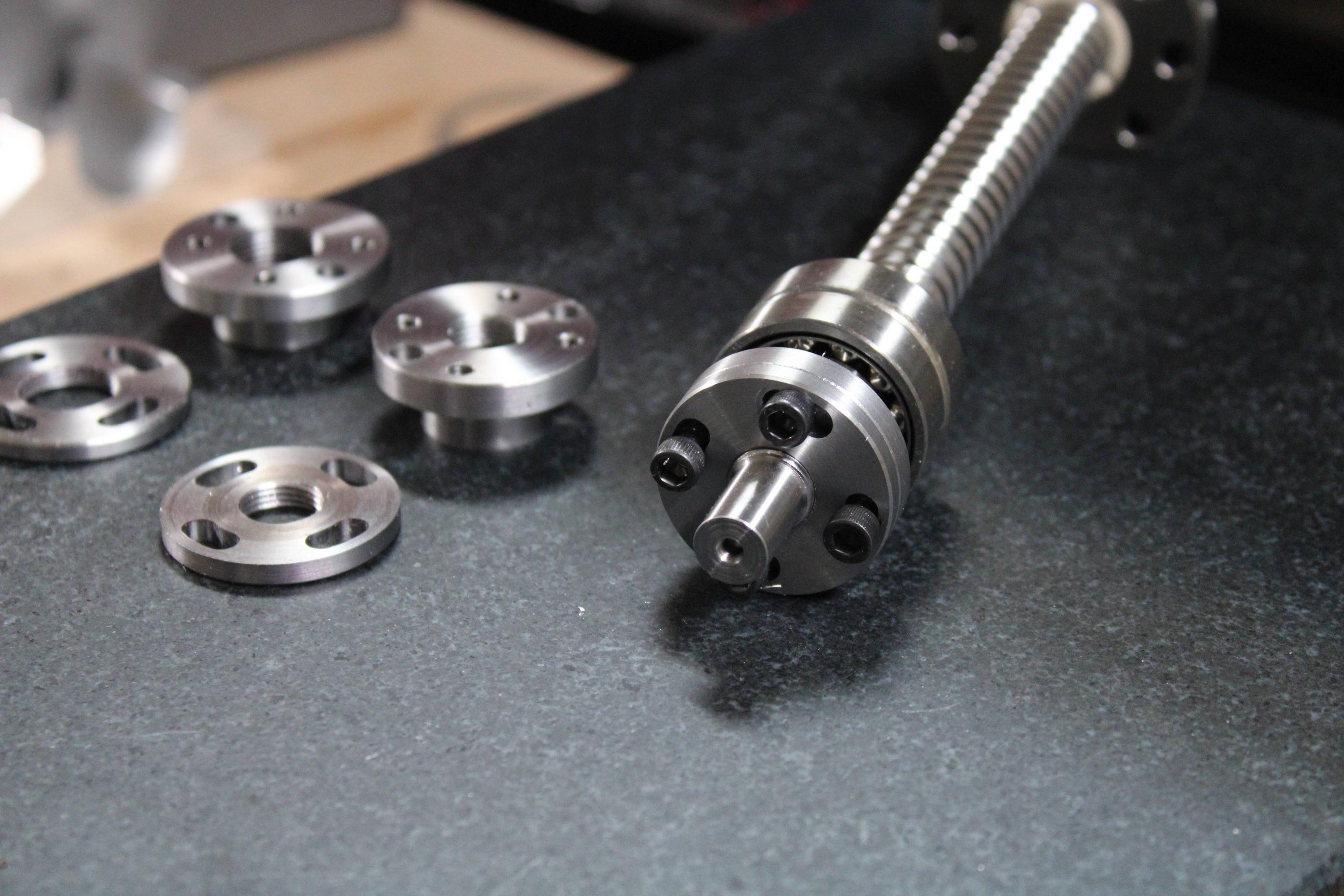
I am just about finished with the new hardware for mounting the new ballscrews and protecting the motors better. I have a pictures to share.

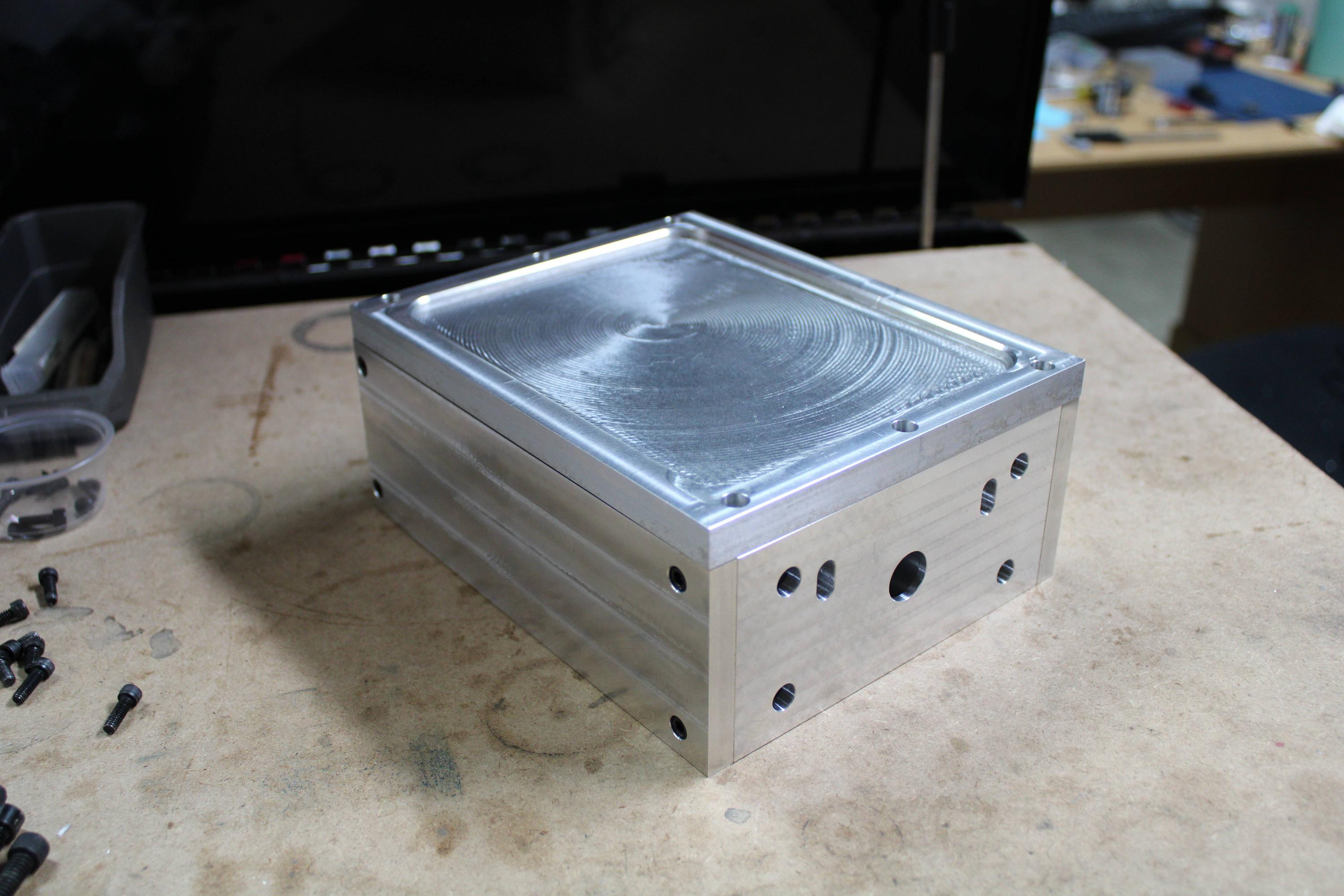
This is the new Y axis assembly with all of the guards installed. This should keep the chips and coolant off the motor, bearings, and coupler.
lPHisfn.jpg


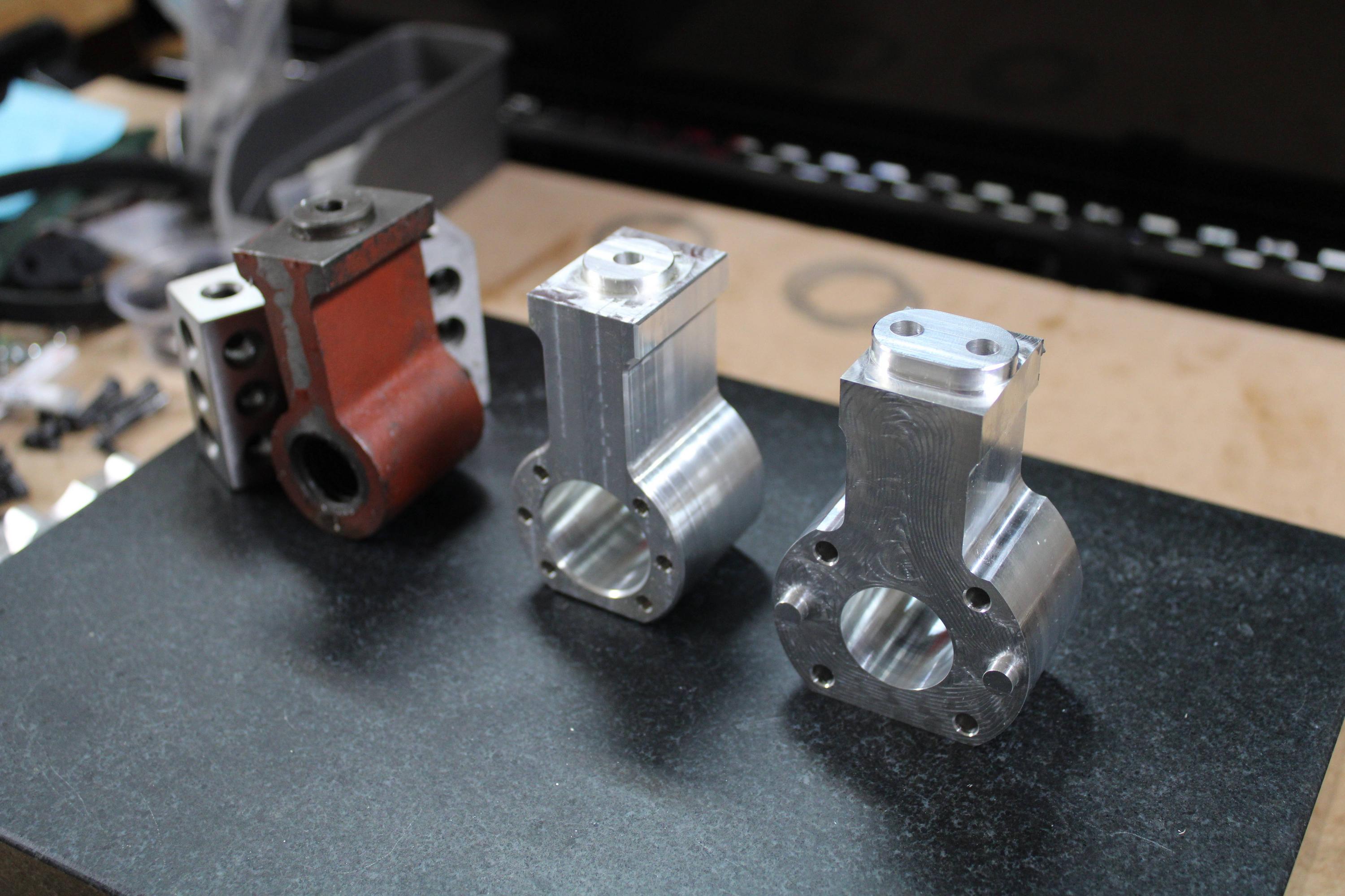
Here it is with the covers removed. I anticipate it being much more rigid with the shorter and thicker risers and a thick motor plate, rather than thinner and longer risers attached directly to the motor.
AG7TMlP.jpg


Another angle.
xNdAcrl.jpg


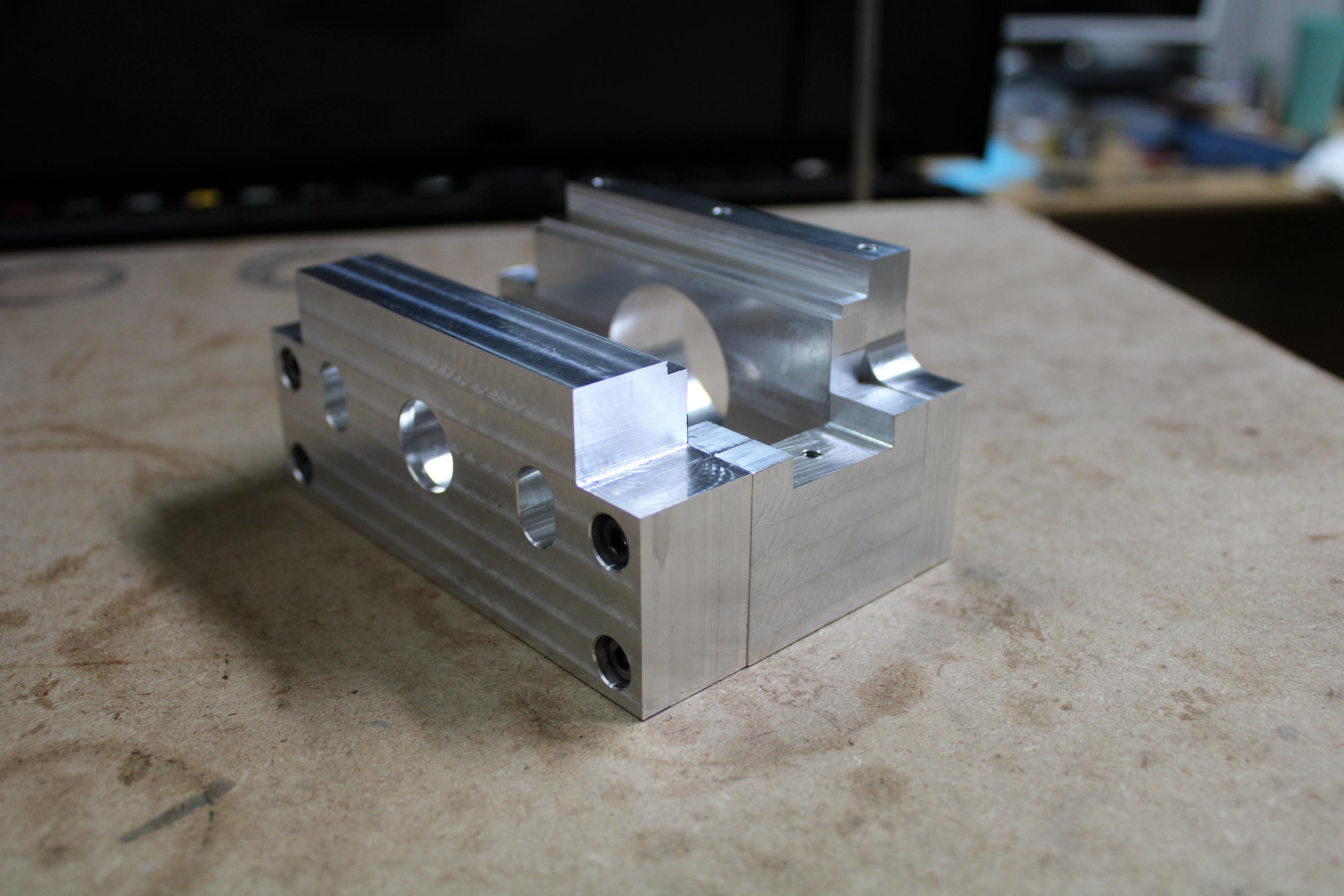
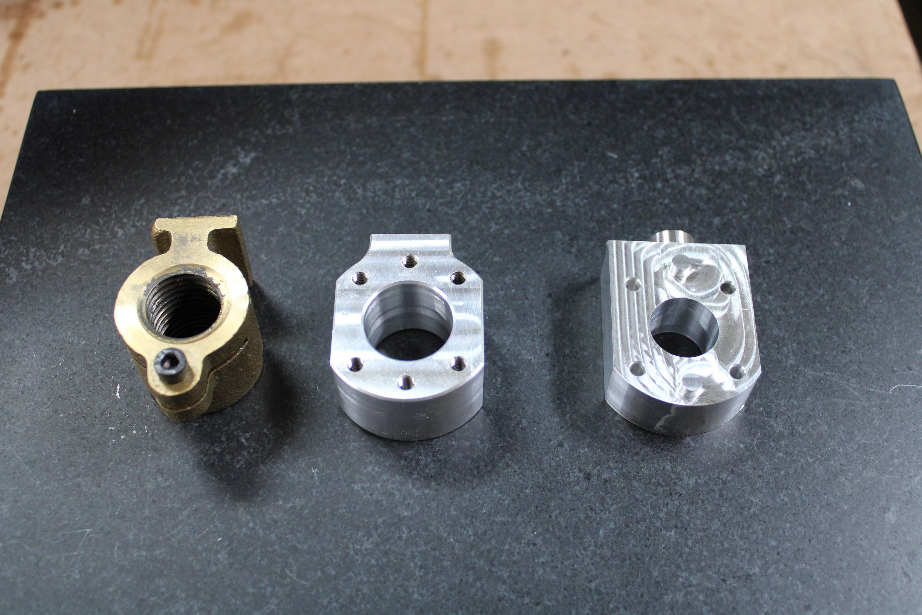
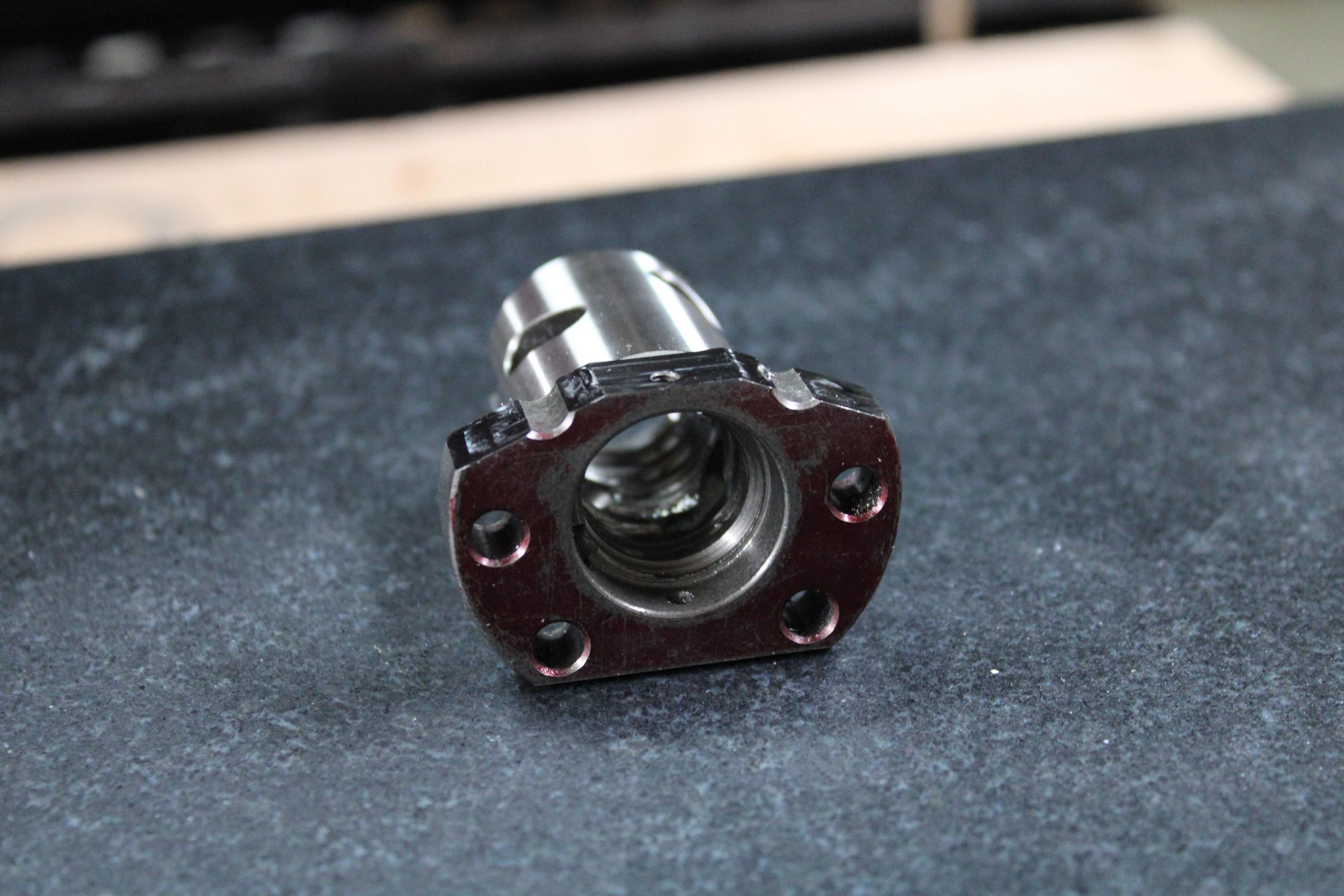
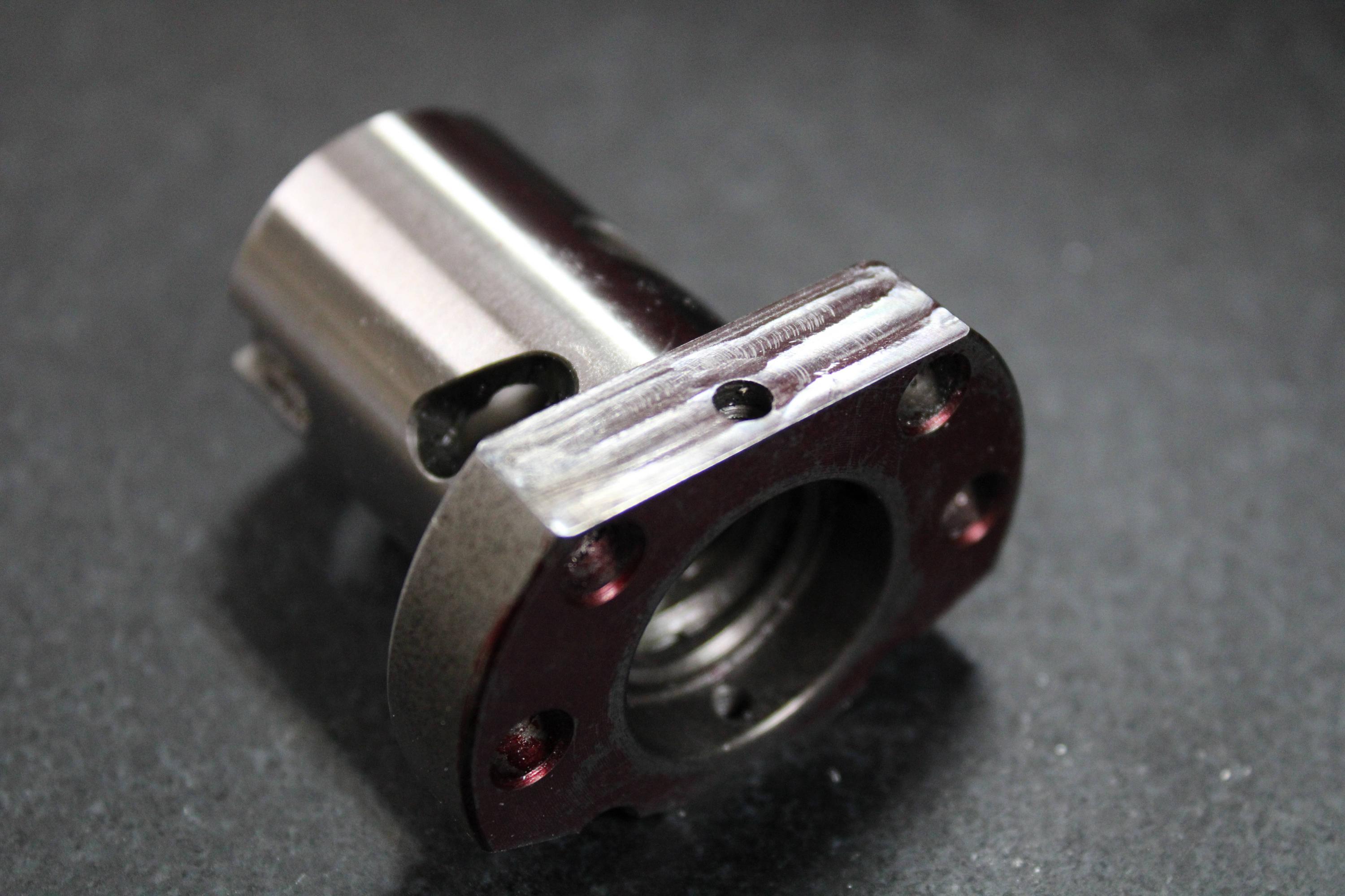
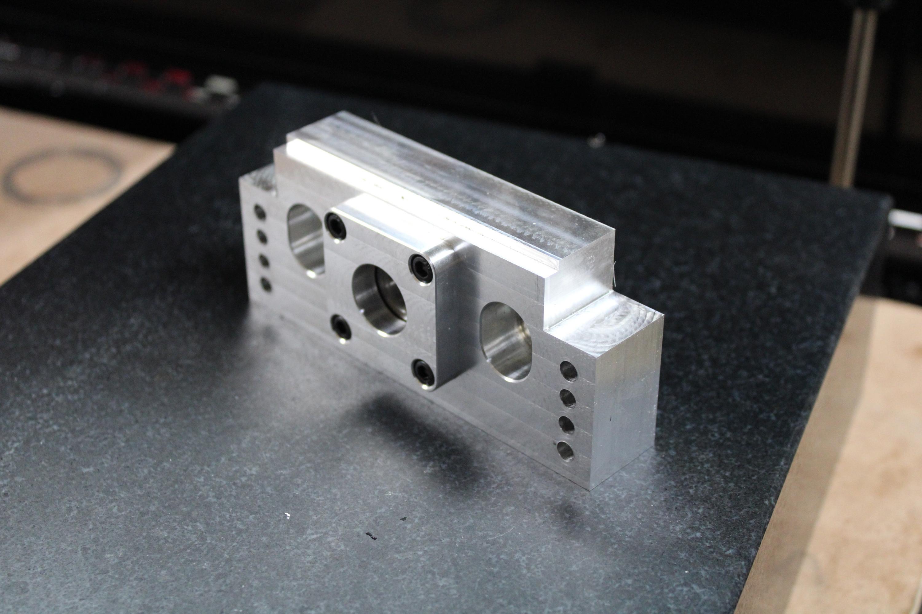
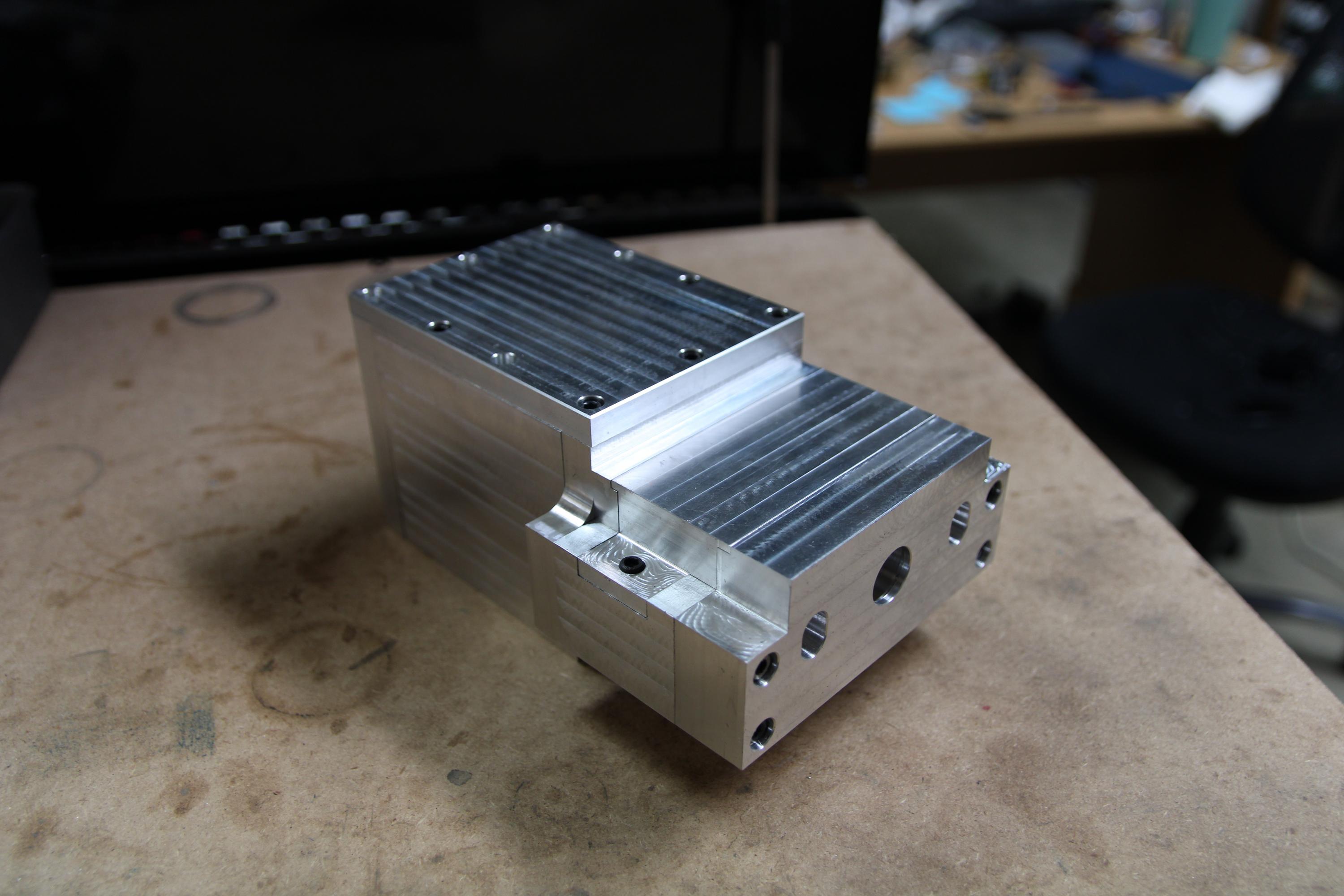
This is the new X axis. This one is also a little bit on the heavy side, but I relieved material everywhere I could to lighten it up. The worst of it is the massive bearing block.
cORVLnJ.jpg


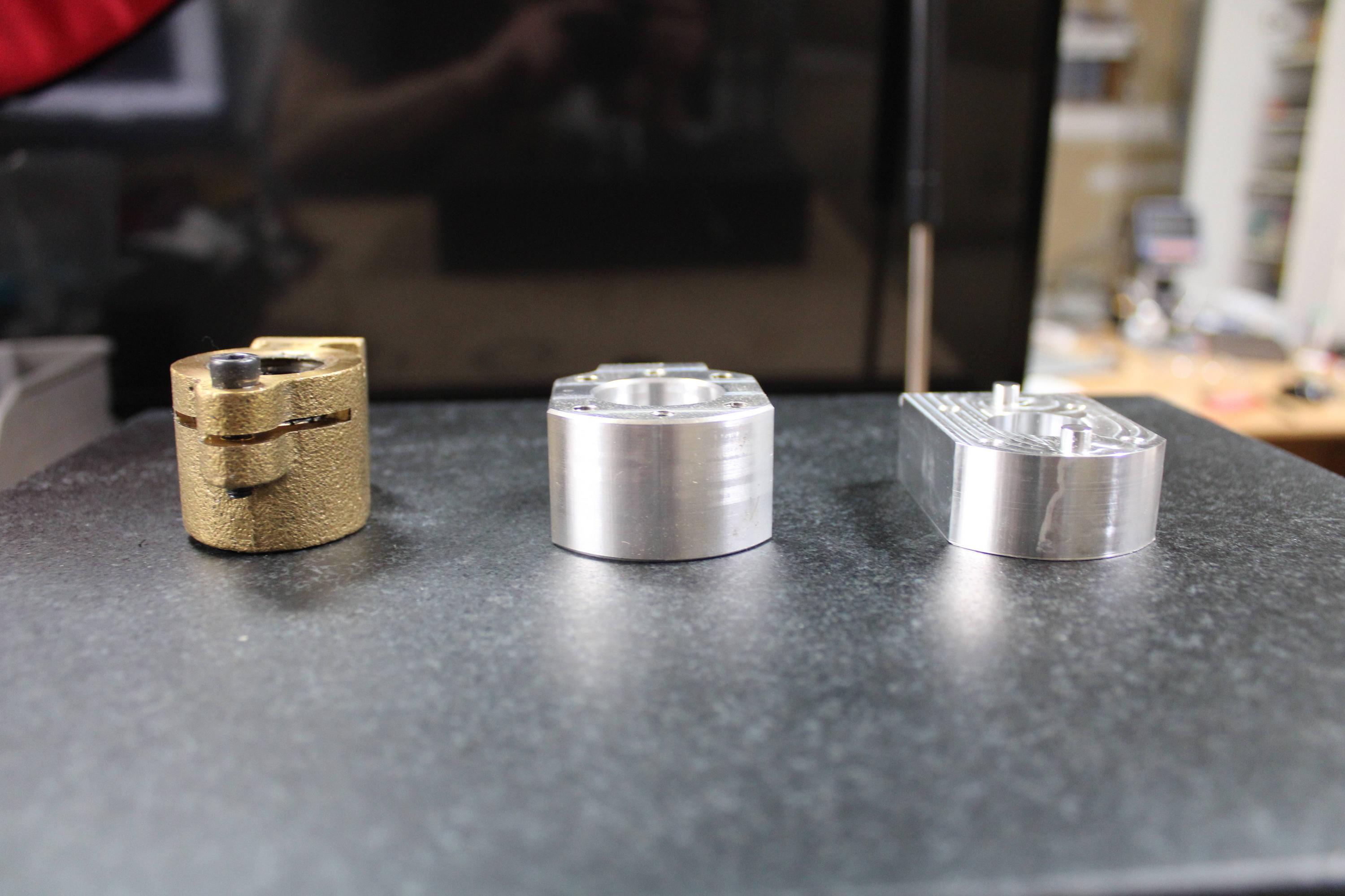
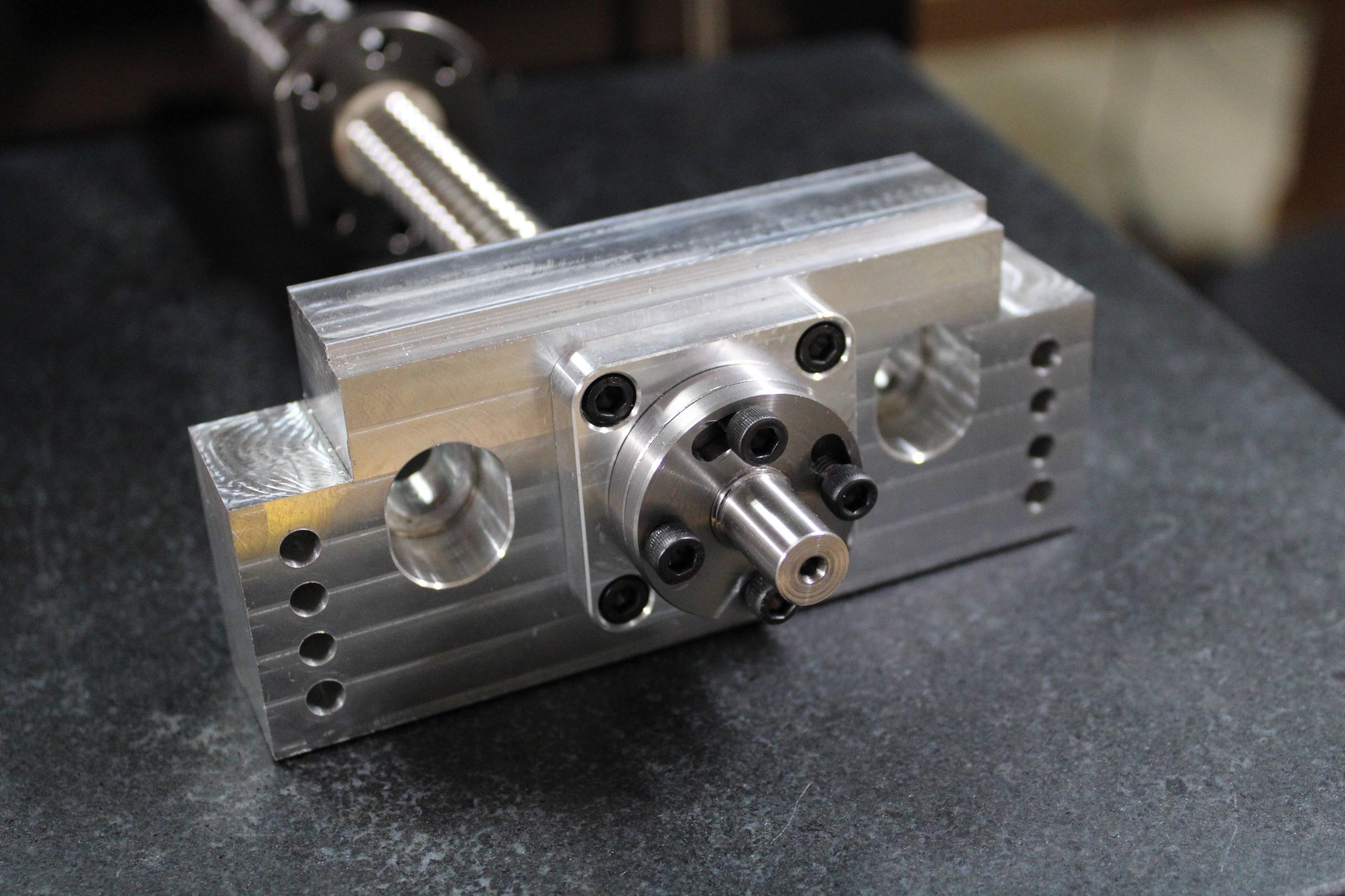
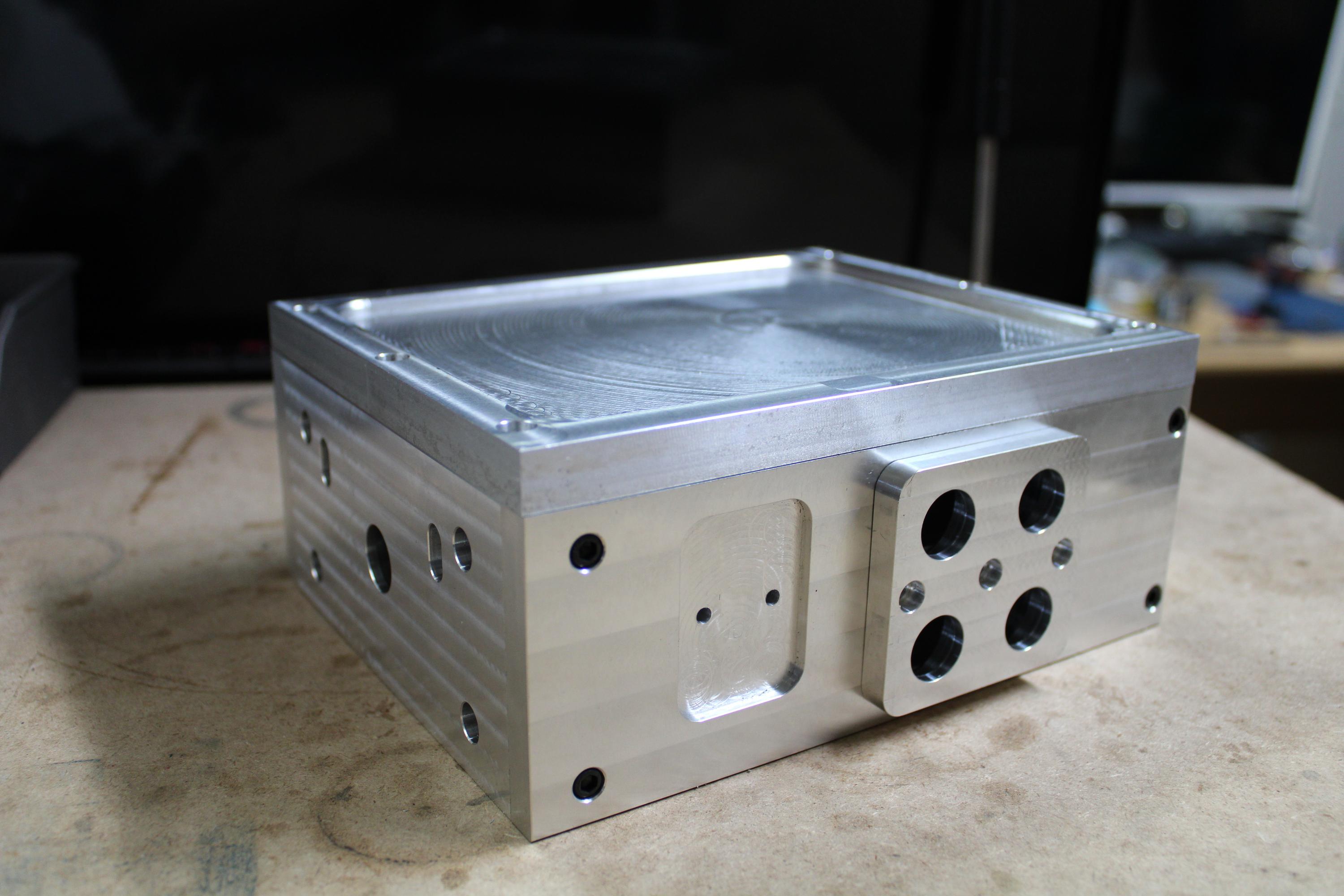
This is the back side. The part on the right will have the electrical connections for the motor (1 for power, one for signal) and the other 2 will be input for the 4th axis and a QD connector for output. This way when I remove the 4th axis, I can just unplug it from the block and cover the connector. The left side is for an air supply. It will have input and output for 2 air connections. One for actuating the brake, one for retracting it. If I ever make a pneumatic fixture or pneumatic vise, the air supply could also be used for that.
O8o7kKm.jpg


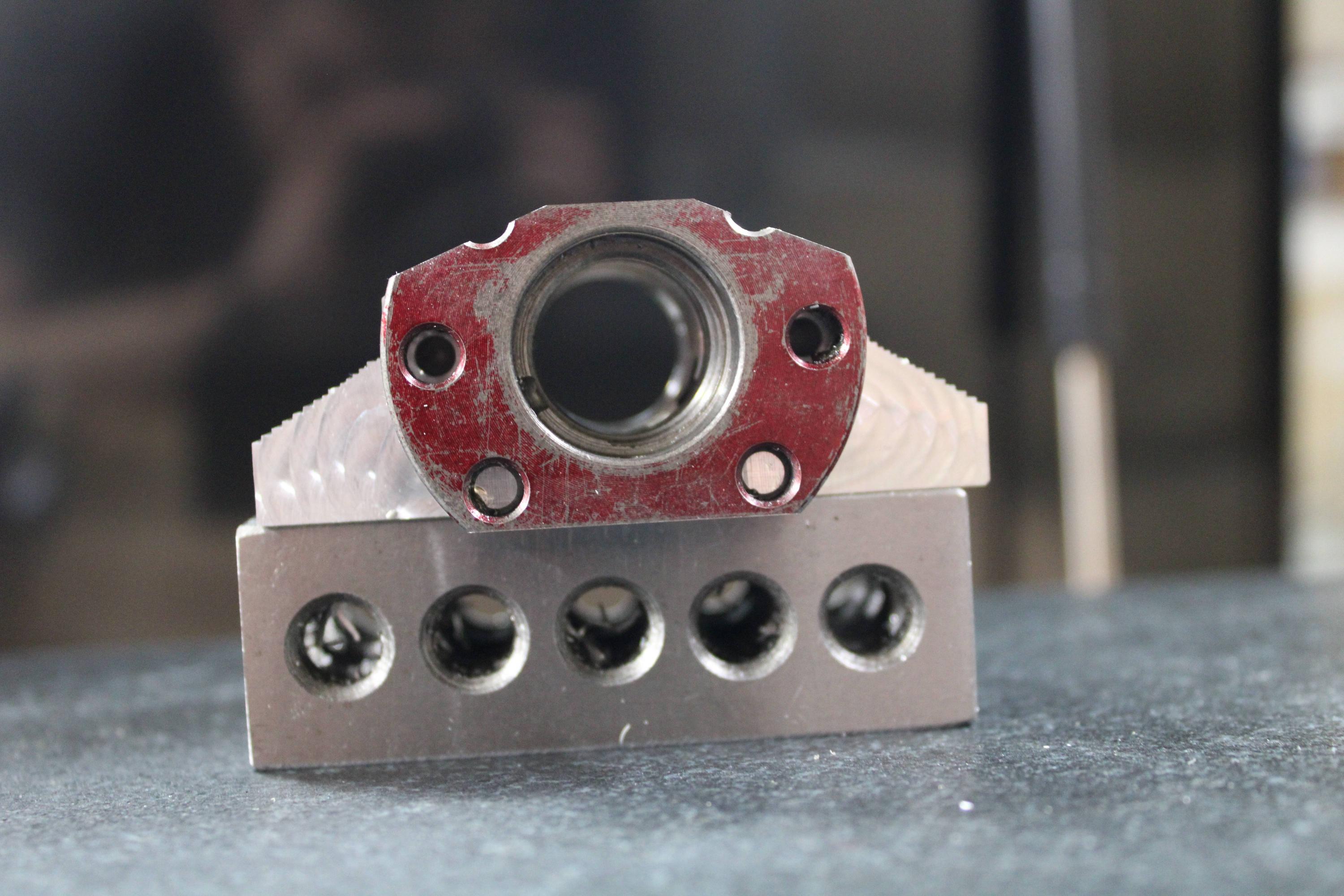
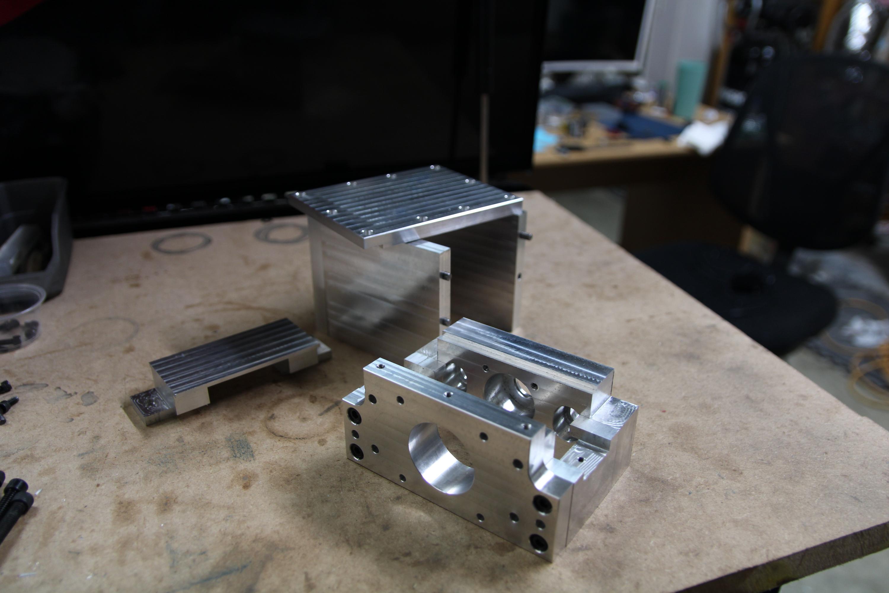
Here is the inside. Again it will be better protected and this design should be stronger than the current set up.
NPhO2jp.jpg


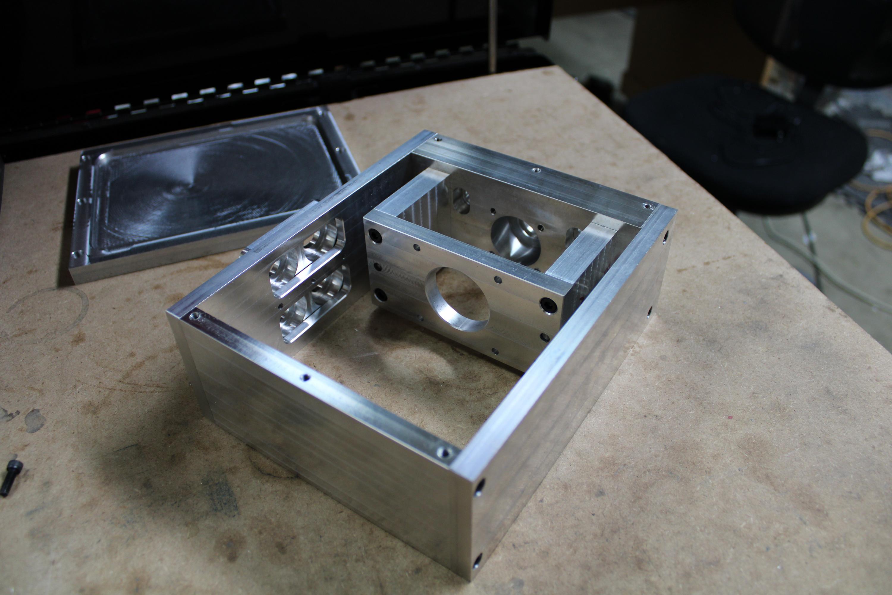
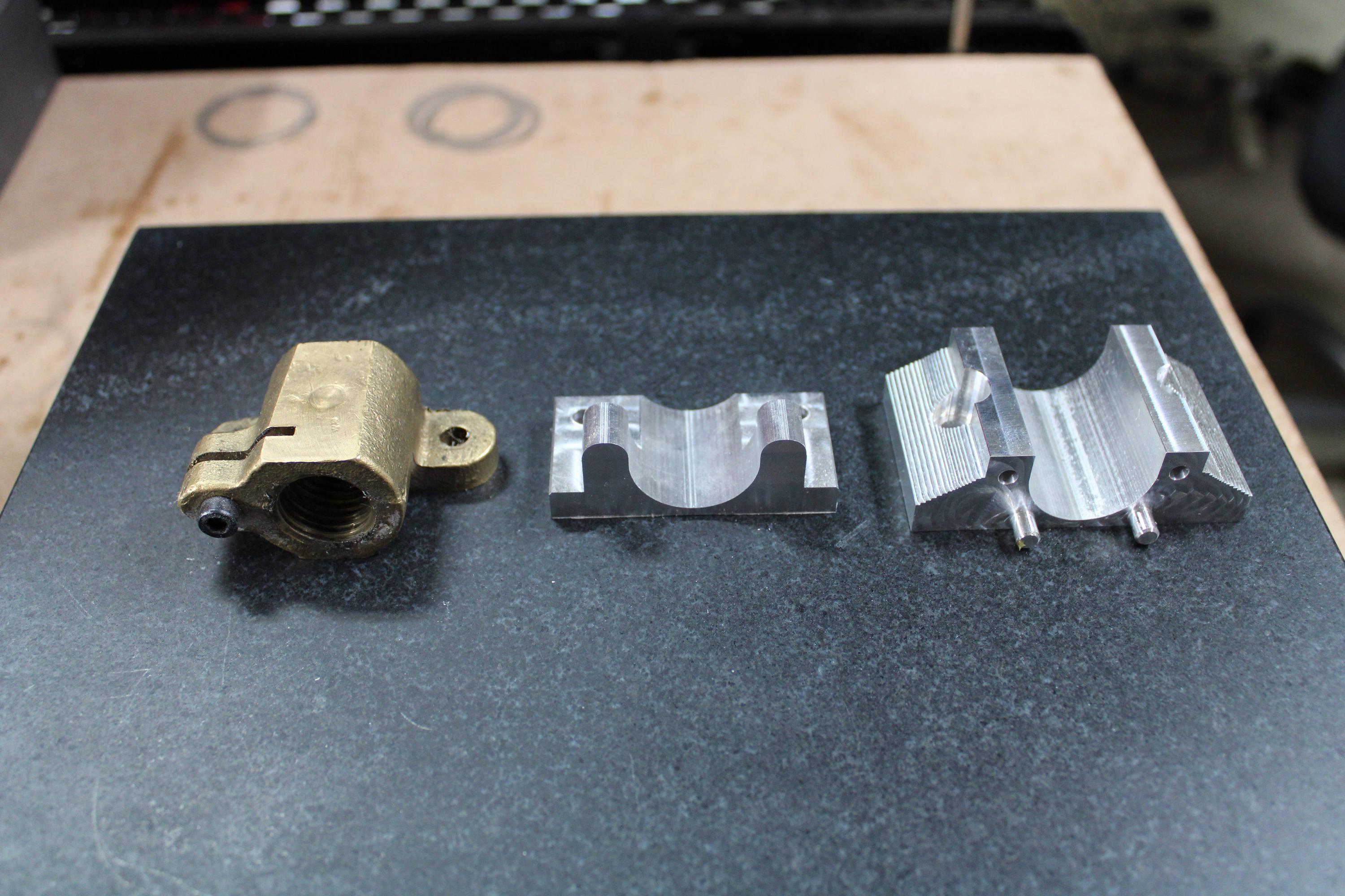
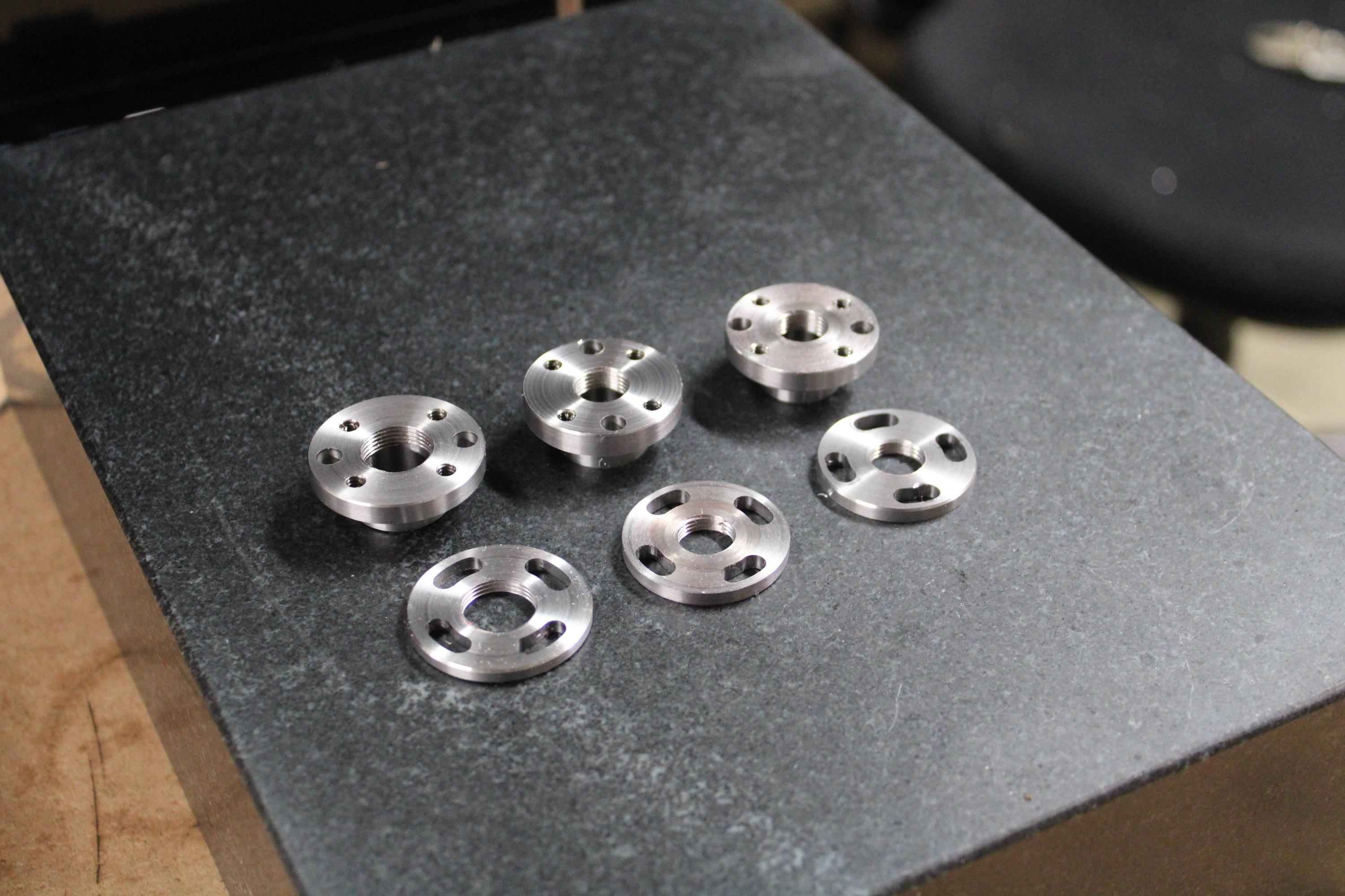
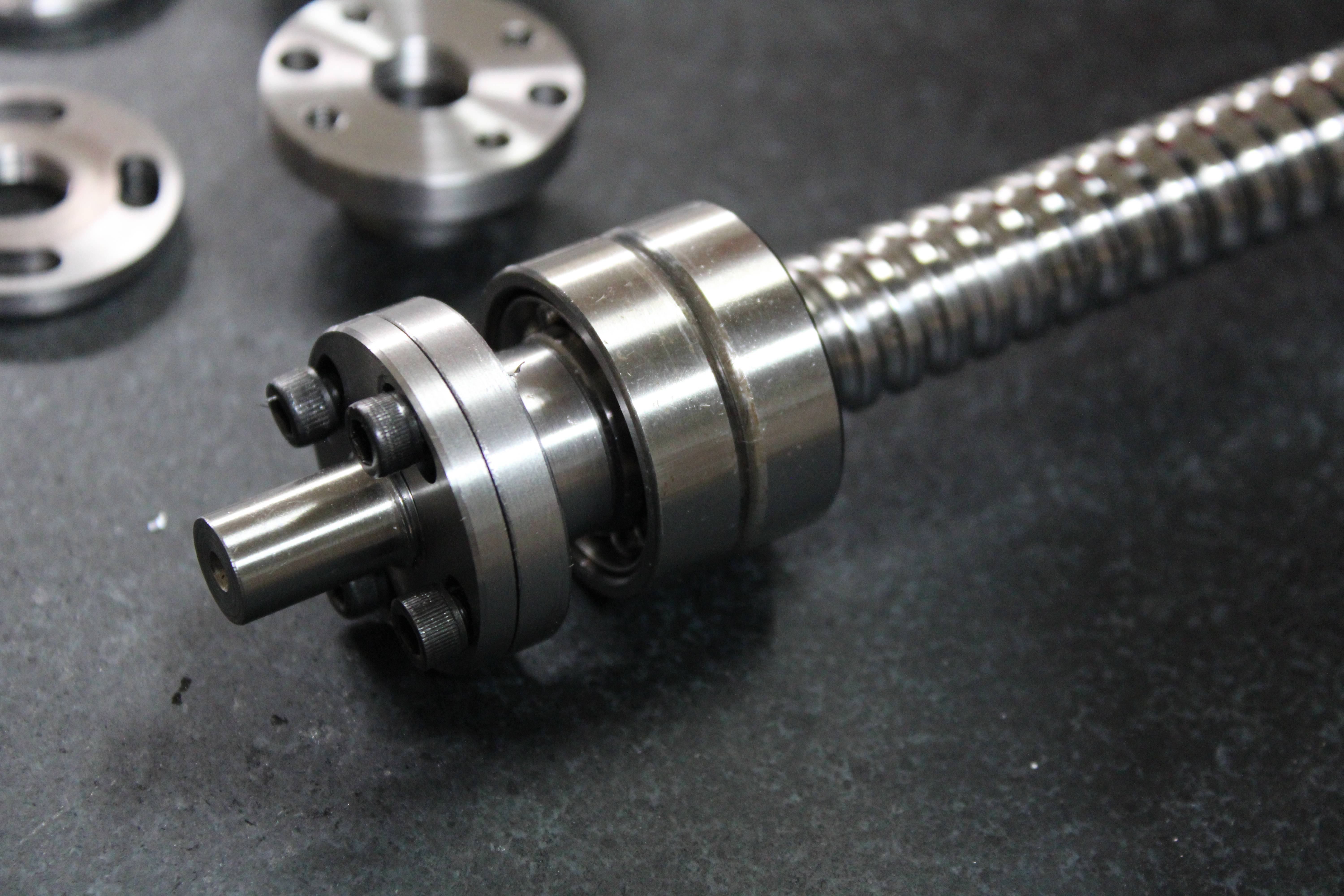
All of the parts use pins to make alignment and assembly much easier, so the fit will be much better than my current design. The pins may also add a little bit of strength to the set up as well.
 
I'm not sure where you are on your 4th axis but I ran across this video of a 4th axis brake. Not sure if you have seen it?


Robert
 
I'm not sure where you are on your 4th axis but I ran across this video of a 4th axis brake. Not sure if you have seen it?


Robert
I have seen that one, and it helped a lot with the design of my brake. I had trouble replicating his design though, so I had to make some changes to mine to hopefully come up with something that works. Right now, my 4th axis is finished, but the brake has not yet been started. The list of projects only seems to grow...
 
I got some more work done this weekend. I now have all of the mill operations done for the new hardware, down to just the lock nuts on the lathe. I noticed I had several different generations of parts, and I thought that made for a good picture.

Each iteration has improvements on the last, so maybe 3 or 4 more and I will have something excellent!

zwfrgHH.jpg


The latest Y axis ballnut mount is thinner, has a smaller hole in the middle (I realized there was no reason to cut out a lot, the screw isn't going anywhere), has 2 bosses machined for alignment, and has a longer boss that goes into the saddle.
9V2UF3D.jpg


nk5IoJL.jpg


The new X axis ballnut mount is for a 20mm screw, also has 2 bosses for alignment, uses 1/4x20 screws instead of 10-32, has space for 2 screws to attach it to the head instead of 1, and has a smaller hole through the middle.
gonVicx.jpg


I also cut the ballnut for the X axis so it will clear the table. It went surprisingly well and the finish was fantastic. I did not think the machine would handle hardened steel as well as it did.
bGT0Gc1.jpg


ik43qBK.jpg


It mounts in the ballnut mount with 2 bosses for alignment and 2 10-32 screws to secure it. This one is significantly beefier than the previous one, and will hopefully lead to a more rigid mounting. The end hangs over a little platform on the saddle, so the ballnut hangs down a little bit past the bottom of the mount.

nFIFpeh.jpg


Once the lock nuts are done and drilled, the mill can come apart and the new parts will go on!
 
That is some cool stuff! Very professional looking parts!
Robert
 
Almost there! I got the lock nuts finished and did some test assembling. The lock nuts are 2 pieces. 1 piece has a flange and holes for a wrench to be used when tightening, then 4 threaded holes for screws to lock the second nut into place. The first nut also acts as a spacer to reach past the flange holding the bearings into the bearing block. There is also minimal clearance between the nut and the flange to minimize the amount of space for chips to get into the bearings if they get past the covers. I have found this sort of lock nut to be very effective, even slightly tightening the screws into place (like rolling the allen wrench between your fingers to tighten) makes it nearly impossible to remove the nuts by hand.

I have 2 for the 16mm ballscrews and 1 for the 20mm screw. I am unsure what caused the browning on the nut in the middle.
72HZO8K.jpg


Here is how they assemble on the ballscrew. The longer nut is relieved so the end can go over the unthreaded portion of the ballscrew and tighten against the bearings.
exuWLHo.jpg


Here is a view of that from the side. I am happy with how that fit turned out. Things don't always come together so nicely when assembling.
YHzyljP.jpg


Here are the bearings installed in the Y axis bearing block with the flange installed as well.
p3JLUzc.jpg


And then the ballscrew installed with the lock nuts in place.
uqdHpCs.jpg


It will be time to pull apart the mill and put all of the new parts on very soon!!
 
How to remove the Z axis leadscrew on a PM-25MV mill. (I couldn't find it by googling, so hopefully the next guy can find this)

It took me a while to get the Z axis leadscrew out because of the way the miter gears are installed. Turns out, you need to remove it all in a pretty specific order.

Step 1. Lock the Z axis gibs so the head stays in place. It might be a good idea to put a note or mark somewhere so you don't forget the leadscrew is out, then unlock the gibs and have the head fall.

Step 2. Remove the column cap.
View attachment 256286

Step 3. Remove the lock nut from the Z axis lead screw while holding the Z axis handle to keep it in place.
View attachment 256287

Step 4. Remove the set screw holding the smaller miter gear to the shaft.
View attachment 256288

Step 5. Tap the shaft out from right to left. The Z axis handle will come out with it.
View attachment 256289

This is what that shaft looks like with the handle removed, but it does not have to be.
View attachment 256290

Step 6. Remove the large miter gear from the Z axis lead screw.
View attachment 256291

Step 7. Remove the key in the Z axis lead screw. If you try to drive it out before removing the key, you will break a thrust bearing. This is what the shaft looks like.
View attachment 256292

Step 8. Remove the screw from the Z axis saddle that holds the lead nut in place.
View attachment 256293

Step 9. Jiggle the lead screw until you get it to drop free, while holding the nut so you can lower it down.

Step 10. Once the leadscrew is free, remove the 4 screws holding the handle plate in place. Then pull straight out. There are roll pins in place so it can only be pulled straight out.
View attachment 256294

Step 11. While holding the nut from the front of the column, unscrew the leadscrew until it is free of the nut. Pull the screw out and then pull the nut out.

Step 12. Nap time, cuz that was exhausting.
Will the leadscrew come out from the top? does the nut and gear need to be removed
 
I really need to chime in on the ball screws. I'm going to sound like a real jerk here, but if one person believes me, it's worth it.

Did you blow up that picture of the ball screw? The o.d. is ground, but the actual threads are not. They are rolled. They are pitted. They do not have a good finish at all.

He didn’t check the thread lead at all. That is the only thing that matters. Most ball screws are going to have some run out.

With a solid set up it works itself out because the ball screw itself is flexible. With the threads in it, and the radius at the root of the thread, they flex. They have to or they would break.


A true ground C5 ball screw of any length cost $4000-$5000 dollars in the U.S.

This is because the lead of the screw is held to .0001” or less. The O.D. size just doesn’t matter. The run out, to a point, just doesn’t matter.


I have spent hours upon hours upon days upon days looking and studying all of this, so I could have an intelligent conversation about it.

What you have seen is not a precision ground ball screw. It is a *******t way of telling you that it is.
 
Did you blow up that picture of the ball screw? The o.d. is ground, but the actual threads are not. They are rolled. They are pitted. They do not have a good finish at all.
Time to break out the microscope! Taking pictures of shiny things is not easy, but what the hell, I will give it a go.

In this picture, you can see that the thread area of the screw has the same finish as the OD. I don't see any pitting but I would say it is a pretty nice finish. In the top left, you can see the rainbow shine that I typically associate with a ground finish.
nh9vWBX.jpg


Another. You can see some chatter in the groove in the center of the thread profile. Not perfect, but the ball never touches that portion so who cares?
Dfnfcdi.jpg


Another.
sZ5dJAc.jpg


Another.
z6aYWgO.jpg


Here is the rolled screw for comparison. Not sure why I couldn't get a decent picture of the rolled screw. It has more of a mirror surface on it which I think confuses the camera.
CX6Jk8e.jpg


Here are the two of them side by side. The picture isn't great, again the camera had trouble getting a good picture with the rolled screw in the shot.
qQdAtcE.jpg


He didn’t check the thread lead at all. That is the only thing that matters. Most ball screws are going to have some run out.
It is ok to address the poster if you disagree. You'll notice that post with the ballscrew pictures and measurements was from the day the screws arrived. It was based on initial impressions and the things I was able to measure. It was not an in depth technical review, it was a quick post about new hardware I was (and still am) excited about.

A true ground C5 ball screw of any length cost $4000-$5000 dollars in the U.S.

This is because the lead of the screw is held to .0001” or less. The O.D. size just doesn’t matter. The run out, to a point, just doesn’t matter.
I am not sure where you are looking, but I have seen dozens for under $600. Tormach mills for example use C5 ground screws and they have replacements available for $550. I think you might also have your tolerances wrong, because a C5 screw tolerance doesn't come anywhere near .0001". The permissible lead error/300mm is .0007" and the error/rotation can be .0003". Even a C0 screw tolerance isn't .0001" or less on the lead.

I will also note that I didn't measure the OD of the screw. I measured the OD of the machined journals to compare to the specifications I requested. Those diameters absolutely do matter if I want a proper bearing and coupler fit.

I have spent hours upon hours upon days upon days looking and studying all of this, so I could have an intelligent conversation about it.

What you have seen is not a precision ground ball screw. It is a *******t way of telling you that it is.
I suppose everyone is welcome to their opinion, but that is quite a claim to make based on 2 or 3 pictures of an item and a few measurements.
 
Ok, I will reply to you directly. The tolerance you talk about is for a C6 ball screw, not a C5.
This not an opinion, it is fact.
I’m happy that you are happy with them.
I just don’t want this posting to mislead people on what they are really getting.
I’ve been machining since 1981. If you can’t grind anything to .0001”, you don’t know how to use a grinder.
Why is it that machine manufacturers can guarantee.0001”?
It’s because they use ground ball screws that are ground to less than .0001”
I’ve also been building machines for the last 10 years.
This is the pic you posted. I blew it up
72BD78FA-B90F-458D-AFE4-4906EA1AFBF3.png
In

I’m sorry, it just doesn’t look that great to me.
Please go find the tolerance ratings.
They are not what you think
I’m really not trying to be a jerk here. I’m just trying to explain how it really is.
 
Back
Top