

-
Welcome back Guest! Did you know you can mentor other members here at H-M? If not, please check out our Relaunch of Hobby Machinist Mentoring Program!
You are using an out of date browser. It may not display this or other websites correctly.
You should upgrade or use an alternative browser.
You should upgrade or use an alternative browser.
POTD- PROJECT OF THE DAY: What Did You Make In Your Shop Today?
- Thread starter wachuko
- Start date

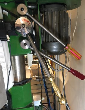
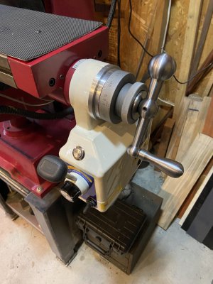
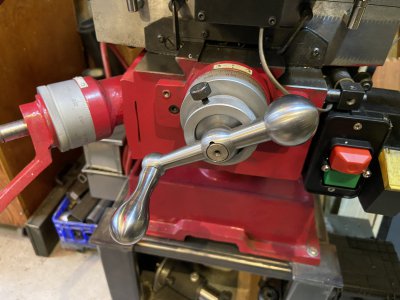
How do you go about getting the nice contour on the handle?Just finished up a set of 3-ball handles for my HF milling machine.
This would be easy with a CNC machine, I would think not so easy with a manual machine.
I used the cross slide on the lathe.How do you go about getting the nice contour on the handle?
This would be easy with a CNC machine, I would think not so easy with a manual machine.
They have some specs in the Machinery handbook, but mine are slightly non-standard to fit the material.
It's easiest to draw the design on paper then take measurements directly from there. As Mr. Pete says, I used CAD (Cardboard Automated Design)
The balls on the big end screw on. The smaller end and machining was done with the part screwed onto a mandrel.
That seems like it would be tricky to get a really smooth contour?
Its a bit like trying to cut a circle with just the X & Y hand wheels on a mill the amount you turn each hand wheel keeps changing, (max on X when Y = 0 , and then the opposite and every possible combination in between. Effortless with CNC, pick a diameter and say go, the computer is much better at calculating and turning the wheels in real time.
Its a bit like trying to cut a circle with just the X & Y hand wheels on a mill the amount you turn each hand wheel keeps changing, (max on X when Y = 0 , and then the opposite and every possible combination in between. Effortless with CNC, pick a diameter and say go, the computer is much better at calculating and turning the wheels in real time.
- Joined
- Feb 27, 2014
- Messages
- 2,131
I've seen mulitple Youtube videos where you use the X & Y to cut a stepped approximation of the curve you want and then use a file to smooth it out. The more steps you put in, the less work with the file.
- Joined
- May 3, 2017
- Messages
- 1,997
My lathe has a very nice factory chip shield for the chuck, but not for the tool post, so I decided to fabricate my own. I've seen several that our members have made, but I was hoping to end up with something a little more compact and versatile. After much pondering with regard to criteria and function, I came up with the following design:
1. It occurred to me that there is sufficient thread exposed at the top of the tool post to attach a holder.

2. I also had two very nice Noga indicator holders that I bought for a project quite some time ago. They have been resting comfortably in one of my toolboxes ever since. I decided one would be an excellent holder for a plexiglass shield mounted to the tool post. So I fabricated top and bottom ends to replace the originals. (I started by attempting to modify Noga's straight end but quickly changed my mind. If I ever needed to use it again as a second indicator holder, I would still have the original parts.)

3. The top end of the fabricated base is drilled and tapped to attach to the holder. The bottom end is milled to a 7/8" hex and drilled and tapped to attach to the tool post. Even though it is hex, it is mounted just barely over hand tight to keep it from slipping. 'Fort-Knox' lockdown is not necessary. The clip that holds the plexiglass is a through-hole on the top face, and 10-32 threaded on the bottom. I used a 1/4" end mill to machine the slot. Since the plexiglass is 0.220 thou, I thought I would need to put a spacer in the slot, but it's very snug without it.


The shield is made out of a piece of scrap clear plexiglass. The Noga body makes it fully adjustable and can be positioned to ride above the chuck shield for close-up work. In addition, it would be a very easy matter to make different size plexiglass shields if necessary. I'm going to experiment with it for awhile, but I suspect I'll end up making an L- or U-shaped shield to direct chips into the cabinet instead of on the floor. We'll see.
Regards
1. It occurred to me that there is sufficient thread exposed at the top of the tool post to attach a holder.
2. I also had two very nice Noga indicator holders that I bought for a project quite some time ago. They have been resting comfortably in one of my toolboxes ever since. I decided one would be an excellent holder for a plexiglass shield mounted to the tool post. So I fabricated top and bottom ends to replace the originals. (I started by attempting to modify Noga's straight end but quickly changed my mind. If I ever needed to use it again as a second indicator holder, I would still have the original parts.)
3. The top end of the fabricated base is drilled and tapped to attach to the holder. The bottom end is milled to a 7/8" hex and drilled and tapped to attach to the tool post. Even though it is hex, it is mounted just barely over hand tight to keep it from slipping. 'Fort-Knox' lockdown is not necessary. The clip that holds the plexiglass is a through-hole on the top face, and 10-32 threaded on the bottom. I used a 1/4" end mill to machine the slot. Since the plexiglass is 0.220 thou, I thought I would need to put a spacer in the slot, but it's very snug without it.
The shield is made out of a piece of scrap clear plexiglass. The Noga body makes it fully adjustable and can be positioned to ride above the chuck shield for close-up work. In addition, it would be a very easy matter to make different size plexiglass shields if necessary. I'm going to experiment with it for awhile, but I suspect I'll end up making an L- or U-shaped shield to direct chips into the cabinet instead of on the floor. We'll see.
Regards