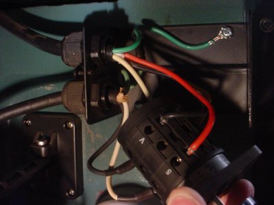
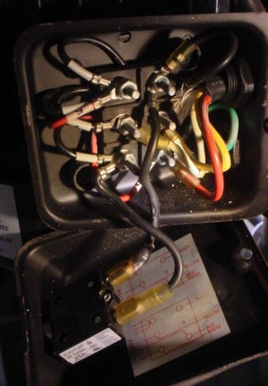
Rong Fu RF-31 RF31 Drum switch & motor wiring

Reviving this old thread to add some info in the hope that it might help someone like this thread has helped me.

I have a Rong Fu RF-45 made in 2013 and it has an almost identical motor and switch wiring setup. I was attempted to convert it to 240v today following the guide on the inside of the motor connections box. Had everything wired up correctly and tested it out. Funny noise and sparks. Shut it off immediately. Rechecked my wiring and everything looked fine. Did some research and found this thread.

Here was the source of my problem:
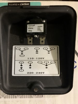
IMG_3907 Medium.jpeg

Looks very similar to the wiring diagram from Werdi. Notice the problem? Not to keep anyone in suspense, the diagram only shows the connections for the motor wires. It does not have the connections for the switch wires. I assumed because there were no switch wires on the diagram that the switch connections were supposed to remain where they were and I just needed to move around the motor wires. That was not the case. Here is the same cover after I have added additional info on the proper wiring scheme. Note the crossed out portions were because I thought I had it right but it was running in reverse.
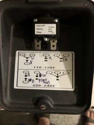
IMG_3912 Medium.jpeg

So using the wiring diagram from Werdis picture I was able to get it setup correctly. Notice that the wiring is the same but the terminals are in a bit of a different order. The motor seems to be working fine even after my inadvertent miswiring.

Just wanted to say thanks to Werdi and Mark because without this thread I would have been lost.
 
That's the goofyest diagram I've ever seen- I don't even understand it
I'm glad you do :)
Did you incorporate the circuit breaker? I see it's not connected to anything
(not that it's really needed- you have one at the wall I presume)
Edit: OK, now I think I get it-the two black dots are unused positions on the terminal strip
 
Last edited:
That's the goofyest diagram I've ever seen- I don't even understand it
I'm glad you do :)
Did you incorporate the circuit breaker? I see it's not connected to anything
(not that it's really needed- you have one at the wall I presume)
Edit: OK, now I think I get it-the two black dots are unused positions on the terminal strip
My box looks almost identical to Werdis with a standard 6 pole terminal strip and all the same colors on the wiring from the motor and switch which also was the same as Werdis. Only difference was his wiring diagram is much better and the poles that were used were in a slightly different order. In the 110v version the lower right pole is just a connection point for the circuit breaker and it had a short jumper to the pole above it. Not sure why it was just not connected directly but whatever. I wrote the layout of the 110v wiring exactly as it was prior to my modifications. The empty dots are just unused or in the case of the 220v lower middle, with the Y, an unconnected wire. The circuit breaker is not shown in the diagram but the black wire is coming from it.
 
Last edited:
I'm about to do this with my Rong Fu. Can someone please clarify:

On post #31, on the drawing on the bottom, are the 4 connections shown from the motor? So 6R, 1W, 4B, Y are from the motor, correct?

Also on post #31, are the 3 connections going into one (5,3,2) from the switch?

Where do the power connections from the plug go on the switch? Is this correct:
On the switch, R and S go to incoming power.
Also on the switch, U and V go to the motor 1 and 4 (black and white). Does U go to 1 and V go to 4?
6 or 5 should go to the motor red or yellow (you only need one). What is the difference between the yellow and red wires? Does it matter which one is hooked up?

Thanks!
 
Those diagrams are confusing. Thing to understand is each of the solid black dots is an isolated terminal post. There are six of them. 5,3,2 are connected to each other on one terminal but there no other wires or connections. Those diagrams in #31 also only show the terminal block and the wires coming from the switch and the motor. They dont show the switch at all.

Let me try to explain my wiring a bit more clearly and hopefully it helps you.

FROM PLUG:
Plug cable comes from the wall containing Black, White, and Green.

  • Black (from plug) is connected to Blue (to switch) using a wire nut.
  • White (from plug) is connected to Grey (to switch) with a wire nut.

AT SWITCH:
There are a total of 6 wires connected to the switch, the incoming Blue and Grey, and then outgoing Red, Yellow, Red, Black, and White.

  • Blue (from power): connected to the switch at input marked S.
  • Grey (from power): connected to switch at input marked R.
  • Red: connected to output marked 5 on the switch (this is not the related to the number 5 in the diagram on post #31).
  • Yellow: connected to output marked 6 on the switch (this is not the related to the number 6 in the diagram on post #31).
  • Black: connected to output marked U on the switch.
  • White: connected to output marked V on the switch.

AT TERMINAL BOX: (this is the diagrams from #31)
There are 4 wires coming from the switch: Red, Yellow, Black, White. These are labeled in the diagram respectively R, Y, B, W. There are 6 wires coming from the motor and labeled individually with numbers 1-6, labeling for these is both in the diagram and on the wire itself.

  • Red (from switch): Connected to #6 motor wire on the top left terminal.
  • Yellow (from switch): This is not used. I have it connected to a terminal by itself (lower middle in the diagrams on #31). I think I tried connecting this one instead of the red to #6 motor wire on the top left terminal block but the spindle ran backwards when on forward so I swapped it with the red.
  • Black (from switch): This gets connected to the fuse button on the terminal box cover, and then from the fuse button to the #4 Motor wire at the bottom left terminal.
  • White (from switch): Connected to #1 motor wire on the top middle terminal.
  • 2,3,5 (from motor): Connected to each other at top right terminal. Not connected to any wires from the switch.

Keep in mind that which of the six terminal posts that are used are not important as they are simply there to allow you to connect wires together and they are not connected to anything if you don't attach a wire to them. The important thing is just which wires come from the switch to the motor. You can look at the pictures from Werdi earlier in the thread and you can see that he actually has a pretty similar wire connection setup its just in a different order on the terminals. Also his wiring diagram is much clearer then mine.

As I said the yellow wire ended up not being needed in my set up. I had it connected to the #6 wire and the red disconnected but my spindle was turning the wrong way so I swapped them.

On my setup switch output U gets connected through the black wire to #4 motor. Switch output V gets connected through the white wire to #1 motor.
 
Last edited:
Thanks for the clarification, much appreciated!

My switch doesn't have any wires, the ones from the plug connect directly. Not all my motor wires were labelled, either. I used the continuity feature on a multimeter to determine which wires were which.

I think my yellow is the correct one to connect for forward motion (I had the red connected and it ran backwards), but I accidently hooked the red and yellow together (instead of the correct way) and blew the switch up (very loud pop, the breaker tripped and the smell of electrical death came from the switch). I have a new switch on order that will take about 3 weeks to get here. The switch shows no outward signs of being fried, except that distinct smell of burnt electrical components. I thought for sure there's be a black mark or something.
 
240 volts is very unforgiving- give us a heads up when you are ready to fire it up again
 
It looks like the switch is okay. I tripped the sub panel breakers and the main breaker for the house.

I wired it back to what I had before I blew the circuit and it spins in reverse when I switch it to forward on the switch, but just hums when I try to go backward. I tried giving the spindle a turn with my hand, but it still would not spin.

I think the yellow and red wires need to be switched to get it to run in the correct directions. That's what I was doing when I blew the circuit, so I put it back to when it worked.

Not sure what's causing the humming. Could the start capacitor be bad? It runs just fine one way, though. Maybe the switch is actually fried?

In this photo, Black from the power (bottom cord) goes to S on the switch and White from the power goes to R on the switch.
DSC01253.JPG

Everything else is connected as described in post #35 EXCEPT: Black is connected to V and White is connected to U on the switch. This is the way it was so I left it.
 
It's still miswired either at the motor or the switch. Can you post a pic of the motor terminal block?
It's best to review from the beginning in cases like this, motor side first
 
Last edited:
Here's a photo:
DSC01255.JPG

Connections as shown:
UL: #2,3,5
ML: #1. White
BL: #4, Black from fuse

UR: Black from switch, black to fuse.
MR: Yellow
BR: #6, Red

I did not see any wires touching.
 
Back
Top