Rong Fu RF-31 RF31 Drum switch & motor wiring

OK looks correct at motor side- I'm thinking the switch could have been damaged by your short circuit
Probably the smart thing to do would be to disconnect the switch and ring it out with a meter
The #5 switch contact might be burned up/melted inside
You could try moving the red wire from switch #5 to switch #6 and see if that works

Connected like so should work unless switch is faulty:
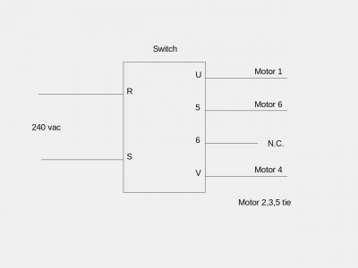
Millswitchdtl.jpeg
 
Last edited:
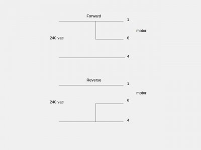
If you want to test the motor itself you can disconnect the drum switch and
do these two power tests: (2,3,5 tied as before)
MotdirFR.jpeg
PS Forward and Reverse might be swapped w/respect to this representation
 
Last edited:
Thanks for the reply.
I had the same thought that I damaged the switch.
I'll try switching #5 & #6 at the switch and see if that works.
How would I "ring out the switch with a meter" to test it?

How do I test the motor? Does one 240v power cable wire go to #1 & #6 and the other go to #4 for forward, with #2, #3, #5 all connected? Sorry, I'm not clear on the diagram. Electrical isn't my strong suit.

I really appreciate the help with this.
 
Motor test:
Yes, 240v line 1 and line 2 go to 1 and 4. 6 is tied to either 1 or 4 for forward or reverse

Ringing out the switch:
A meter set on "ohms" is required to test continuity. Use the "beep" mode if provided.
Or a simple battery and light bulb tester could be used instead.
Switch is disconnected completely from machine.
In center off position should be no connection between any terminals
No connection should be seen between any of the following pairs in any switch position:
R to S no connect
U to V no connect
5 to 6 no connect

R and S connect to U and V for both forward and reverse (R to U and S to V for example)
5 and 6 connect to R and S but swap positions for forward vs. reverse
In other words:
For Forward, 5 may connect to R and 6 may connect to S
Then for Reverse, 6 may connect to R and 5 may connect to S

Note: Some switches may swap U and V rather than 5 and 6, with respect to R and S
Clear as mud, right? :)
 
Last edited:
Power test was a success. It worked in both directions. Does this mean the capacitor is good?

Connection test results. Yes means I had continuity, no means I did not:

connection/FWD/REV (these might have been reversed)
R->U yes/yes
R->V no/no
S->V yes/yes
S->U no/no

6->R yes/no
6->S no/yes
5->S no/no
5->R no/yes

5->U no/yes
5->V no/no
6->U yes/no
6->V no/yes

If it's not too much trouble, someone let me know what, if anything, the test results mean.

I took the switch totally apart. It still smells like burnt electronics and there was some black on some of the switches (R, U, V). Some cams fell out and I was not able to figure out which way they went so I need to wait until I get the new switch before hooking this up. It arrives end of August.
 
Yep switch is toast. #5 failed the tests.
You could wire the motor to run in one direction while you wait for the new switch
(capacitor is good, btw)
Be careful around 240 volts, now you've seen what it can do
 
Last edited:
I got the new switch, however, it is labeled differently, even though it is the same part number. It has 1-12 on it.

Here's my best guess based on orienting the switches the same way and seeing which connections lined up:
NEW=OLD
4=5
12=V
1=R
9=5
2=U
10=6

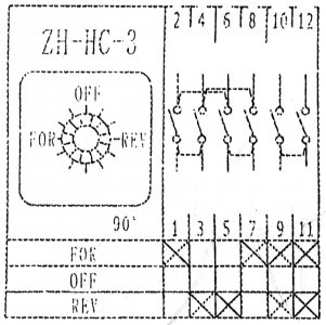
The switch came with this wiring diagram:
mill switch wiring diagram new.jpg

I'm not sure how to decipher it. Any help would be much appreciated. Thanks!
 
OK I see-and no, your guesses are a bit wrong I think. Don't hook it up yet
Those jumpers shown on the new diagram- are they integral to the switch? Those dotted lines, are they just "suggested" jumps
or are they really inside the switch?
For example, are 9 and 11 permanently tied together? You should check with your meter all those
pairs that seem to be jumped. So 1 and 3, 5 and 7, 2 and 6, and 4 and 8 should be checked as well
Let me know what you find..
 
Last edited:
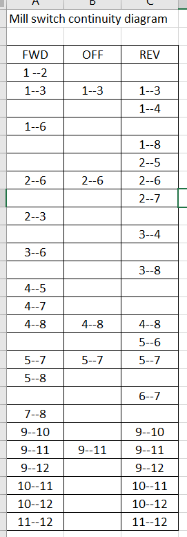
Hopefully this will help. It's a chart of the continuity between all the connections:
mill switch wiring continuity chart.PNG

Looks like the ones you mention are all tied. What does that mean?
 
Means you are hosed
LOL well, not totally hosed but it's very different than the old one
I think we can still use it though- give me a bit, I'm helping two other members also
I'll do a sketch or list when I get a minute
OK:
1 --- U (motor 1)
5 --- V (motor 4)
9 --- 5 (motor 6)
2 --- R (power 220v)
4 --- S (power 220v)
Add jumper wire from 8 to 10

Before you plug it in/fire it up, check across the power plug prongs with the switch in the off position
Should be no continuity- then in both forward and reverse you should see a few ohms resistance (of motor windings)
If you see a dead short nearly 0 ohms there's a wiring error- check wiring
 
Last edited:
Back
Top