Thinking of joining the RF-30 club, but I got some questions...

I vote for the 4" vise. I got my 4" from Shars on sale for around $100. That might have also included the shipping. Don't remember. IMHO the 4" is a perfect fit on a RF 30. Mine came with a swivel base which I removed. I made a backing plate for the swivel base that fits my chucks. Not as good as a rotary table but still very useful at times.
 
David & Chuck:

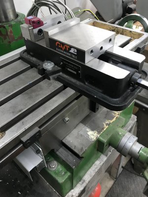
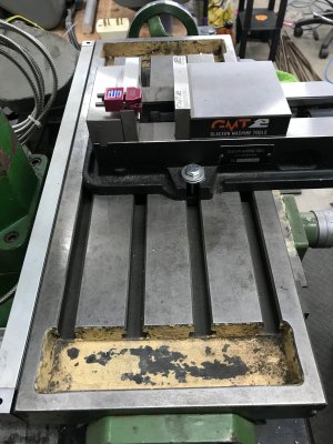
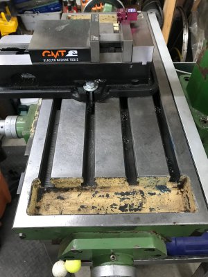
Would you mind posting a picture of your vises on your mills? It'd give me a better idea of what these look like. No rush.
 
I could move it forward one slot and not lose any Y-axis travel.
image0.jpeg

image1.jpeg

image2.jpeg
 
Last edited:
Here you go. My vise and the swivel base live on the table. I have the coordinates written down to center the swivel base under the quill. I never just randomly move the head. If I need to move the head I set up a DI so that I can bring it back to alignment with the vise and with the swivel base.

IMG_3922.JPG
 
Measured my RF 30 clone for you. My table is 29" wide. On mine the distance from having the table all the way to one side to moving it all the way to the other side is 60 inches. That includes the 3 1/2" handles on each wheel.

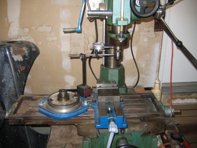
You see all kinds of contraptions that people have come up with to keep the head aligned. I use a dial indicator on a magnetic base. Quick and simple to use.

View attachment 340929
 
12. VISE (continued)
David and Chuck: Thanks so much for the timely response! I was concerned about the size because my current mill vise only opens to 3" and I thought 4" wasn't much bigger. Shars has a 5" vise (#202-1001 or #202-1022) that is not too much bigger, about 1.2" longer (measured along the Y-axis), including the handle, about 1/4" wider (X-axis) and about 3/8" higher (Z-axis). The 4" vise looks good, but what about the 5"? It gives me lots more room, but maybe it's just a little too big, meaning limits to the Y-axis travel. I'll have to see if I can get that dimension. I figure I'm considering a bigger mill to make bigger parts; no sense in having the vise be too small. Thoughts?

I edited the posts to number the questions so we could keep track.
 
My vise has pretty generous capacity:
4" capacity between the inner jaw plates.
11" capacity between the outer jaw plates by moving the jaws to the outside.

A key factor is the distance from the front of the vise to the mounting lugs. As this distance increases, the vise has to shift toward the operator so it doesn't bump into the column. So the benefit of additional capacity might be hampered by the loss of Y-axis travel.
I think the biggest question is what kind of work do you expect to do?
 
13. CHANGING SPEEDS
I was looking at the instructions I downloaded and it appears that you just loosen the bolts on the middle pulley to loosen the belts, then move them to the desired pulley. Is that correct? How much of a pain is this? I'm pretty tall, but I might have to stand on a stool.

14. CHANGING TOOLS
IIRC, the spindle on this machine had some splined shaft sticking out the top. 3-01 on the "Complex Machine" parts diagram, but it might've been 3-17. Is there a special wrench to hold this? I don't think it was a hex bolt, but I could be wrong. I DO remember a large hex bolt (about 2" A/F), but didn't think this was the right one. In any case, how hard is it to change tools? Seems like there'd be lots of opening and closing the top cover.
 
My vise has pretty generous capacity:
4" capacity between the inner jaw plates.
11" capacity between the outer jaw plates by moving the jaws to the outside.

A key factor is the distance from the front of the vise to the mounting lugs. As this distance increases, the vise has to shift toward the operator so it doesn't bump into the column. So the benefit of additional capacity might be hampered by the loss of Y-axis travel.
I think the biggest question is what kind of work do you expect to do?

This whole process started when I was designing a ball turner for my lathe. The yoke that holds the part that holds the blade is 4" high so it doesn't fit in my milling vise. Mine does not allow for putting the jaws on the outside, and anyway, they only stick up about 0.10", which is not enough to clamp anything safely. I had to redesign it in 3 pieces so I could make it. I also need room to insert a piece of round drill rod (1/4" or so) so I can square up pieces. So, anything that is bigger than about 2-3/4" won't fit. That really limits what I can make. It makes for an interesting design challenge, but also is a PITA.
I thought a 5" vise would give me enough room, but not be too big for the mill.
 
13. CHANGING SPEEDS
I was looking at the instructions I downloaded and it appears that you just loosen the bolts on the middle pulley to loosen the belts, then move them to the desired pulley. Is that correct? How much of a pain is this? I'm pretty tall, but I might have to stand on a stool.

I can change the belt positions in about a minute. I keep the necessary wrenches near the machine. That said I installed a 3-phase motor and VFD which greatly reduces the need to change belt positions.

14. CHANGING TOOLS
IIRC, the spindle on this machine had some splined shaft sticking out the top. 3-01 on the "Complex Machine" parts diagram, but it might've been 3-17. Is there a special wrench to hold this? I don't think it was a hex bolt, but I could be wrong. I DO remember a large hex bolt (about 2" A/F), but didn't think this was the right one. In any case, how hard is it to change tools? Seems like there'd be lots of opening and closing the top cover.
There is a special wrench (I cannot recall the name of it...) to hold the spindle so the drawbar can be loosened. On my machine I don't have to remove the cover because it has a hole above the spindle. I've never had to secure the spindle to loosen the drawbar. My mill has an MT3 taper not R8 so the need to secure the spindle when dealing with the drawbar may differ for an R8 spindle.
 
Back
Top