Wanting to power a lead screw

Then you needn't worry about it.


If it works you're ok.


Right.

Then the heat sink for that board must not be hot. It's a design tradeoff. Some engineers will do it one way, some the other.

Thank You John.

So, IOW's, I should be able to, (won't sue you if something happens............LOL...........) ground the heat sink, and/or mount the heat sink to the DP frame and ground the DP Frame?

BTY,
got it mounted last night, just have the board hanging there for now, but like I was saying,
The mounting on this TM motor is Sweet!!
"Baby 56 frame" for sure.
Mounting bracket on motor matched right up with DP motor mount,
5/8" keyed double ended shaft, (keyed on both shafts) So a off the shelf pulley was able to be used.
And was able to use my same belt.

What is nice about this (double ended key way'ed shafts) is, as it looks like the motor brushes are in there at an angle, l would say it's best to run it in the factory designed direction only.
But if I needed the other direction, I could just flip the motor end for end 180*.

One thing I did notice, at real slow speed, (sort of a crawl) I can stall the spindle by hand, and the controller does not try to compensate for the stall.
Maybe I can try tweaking the IR compensation pot for this.
But so far I think it is pretty cool.
As far as breaking the center wire to the pot, so I can re-start at the speed I stopped at, I don't think I will. It is pretty easy to just judge the speed I had it set to before.
One thing I did adjust was the Max speed, I don't think I need it quite as fast as the board was allowing.
 
Bumped up the IR comp, and now when you stall it, the board senses it, and speeds the motor right up.
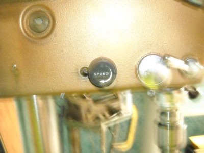
I am having trouble getting good pictures, only have one of the pot that came with the TM, mounted on the DP.
Think it is pretty cool the way it says "Speed" on it.

DSCN0171.JPG
 
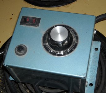
OK, got the Treadmill board mounted in a nice little box that had a switch on it already, you might recognize it from the beginning of the post, l took the board and pot out of that box, and installed the treadmill board and pot.
Made for a pretty clean job.
Plus the box was given to me.
And the treadmill was given to me.
Total cost,; Nothing.
Here is a short video on you tube showing the drill press set up.

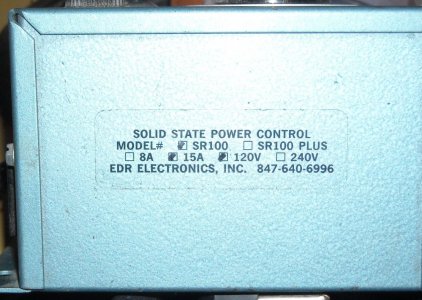
Solid state 1.jpg Solid state 2.jpg
 
Last edited by a moderator:
Thanks for this thread. It gave me the incentive to add a drive to my lathe. I did an article with pictures here:
www.rvbprecision.com

nice work on your conversion.

thanks
 
Thanks for this thread. It gave me the incentive to add a drive to my lathe. I did an article with pictures here:
www.rvbprecision.com

nice work on your conversion.

thanks

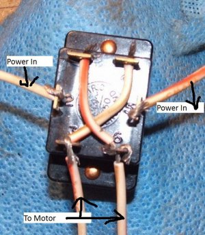
Boy, you really did a nice job on that, when you tie in the new switch for forward and reverse, did you have to chris cross wire the DPDT switch? like in this picture.
I don’t really like the switch that came on that board either.

Talking about the forward/reverse for the lead screw.
I had never thought of using both high and low speeds.
I hope my wiper motor is happy running in both directions.

Oh, and to wire the motor for 2 speeds, would I just run my negative wire out of the PWM board straight to the motor, and my positive wire to the center lug of a SPDT switch, and the two motor leads, high and low to the outside lugs of the spdt switch; Correct?
Has to be, just 2nd guessing myself I guess.

switchwire.jpg
 
Last edited:
Thanks for this thread. It gave me the incentive to add a drive to my lathe. I did an article with pictures here:
www.rvbprecision.com

nice work on your conversion.

thanks

rbertalotto, your mod turned out terrific, great job! It kind of makes you wonder why it didn't come that way from the factory huh... well, now it is. :)

mrbreezeet1, sweet job on your drill press, really like how you re-purposed the box and speed dial, cool! In your vid I see a chain on the back side of the press, is that a power table lift as well?

Wow, it sure has rpms too doesn't it. Do you have a readout planned for monitoring rpms? If not, here's a cool kit I saw mentioned recently on this forum:

MachTach
http://www.machtach.com/Gallery.html

http://www.machtach.com/Buy.html
 
Thanks Bob, Yeah, someone had given me that box, and Jim said I couldn't use it for what I had wanted, so I thought I may as well use it here.
The guy said "If you can use it. I could have it"
He didn't say it had to be as the box was originally engineered.
It had a 110 volt female outlet on it too, I was going to wire in for the work light, but it was getting too bulky in there. (crowded)
No, that chain just has the chuck key on it.
Was not planing a readout for the rpm.

I might steal rbertalotto's Idea for mounting my power supply. I was thinking about mounting the PWM and the power supply all in one box, but did you notice where he has his power supply down on the side of the lathe stand?
My power supply is already in a box, so may as well just mount it by it self.
 
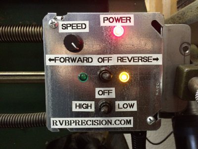
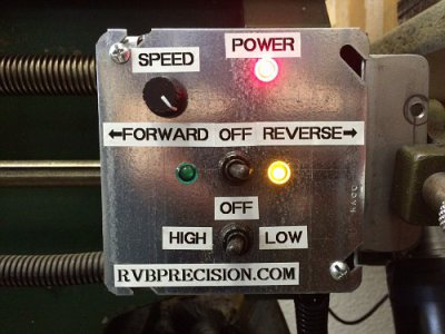
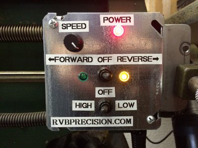
Yes, I had to wire the DPDT switch exactly as you have in the picture. The controller I bought had the F-R switch prewired. I replaced the switch with a mini weatherproof (cutting fluid proof) switch.

Today I added a few LEDs to the control panel. The controller has LEDs mounted on the circuit board that I removed and replaced with panel mount versions from Radio Shack. I'll update the web site article with part numbers etc.

Now that's funny... when I saw your video I thought it would look cool to have LED indicator lights on the box but didn't want to mention it fearing I would sound nit-picking. :) Can't wait to see the latest vid...
 
Back
Top