

-
Welcome back Guest! Did you know you can mentor other members here at H-M? If not, please check out our Relaunch of Hobby Machinist Mentoring Program!
- Forums
- THE PROJECTS AREA
- PROJECT OF THE DAY --- WHAT DID YOU DO IN YOUR SHOP TODAY?
- Project of the Day Mega-Thread Archives
You are using an out of date browser. It may not display this or other websites correctly.
You should upgrade or use an alternative browser.
You should upgrade or use an alternative browser.
2020 POTD Thread Archive
- Thread starter eugene13
- Start date
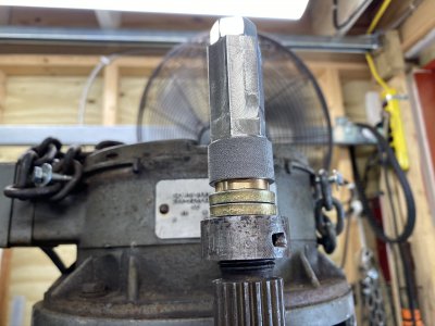
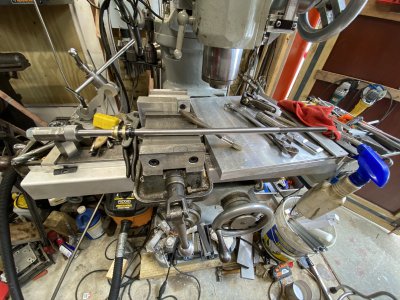
My Millrite milling machine had a fairly bent draw-bar when I got it. Also a vibration and I can see the spindle step pulley has a bit of a wobble. I used a torch and did the Keith Fenner method of shaft straightening. That was more of a “ let me see if I can learn this skill” sort of thing than a let me fix my draw bar sort of thing.
It was a decent improvement but still not perfect by any means.
So I decided to see if I could get some of the vibration out.
I removed the step pulley and cleaned up the bottom of the step pulley by taking a few cuts on the lathe.
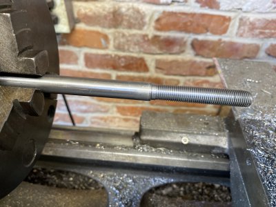
I then made a new draw-bar. Nothing special here. Used some 1/2” 12L14 for the main body and cut the threads....1/2-13 one side and 7/16”-20 other side using dies. Only problem I ran into was I wasn’t careful enough when cutting the 7/16” threads and they turned out with the die threading with a small amount of wobble as it was cutting threads. Luckily I made the shaft about 4” longer than the original bar.
It was a decent improvement but still not perfect by any means.
So I decided to see if I could get some of the vibration out.
I removed the step pulley and cleaned up the bottom of the step pulley by taking a few cuts on the lathe.
I then made a new draw-bar. Nothing special here. Used some 1/2” 12L14 for the main body and cut the threads....1/2-13 one side and 7/16”-20 other side using dies. Only problem I ran into was I wasn’t careful enough when cutting the 7/16” threads and they turned out with the die threading with a small amount of wobble as it was cutting threads. Luckily I made the shaft about 4” longer than the original bar.
Attachments
Last edited:
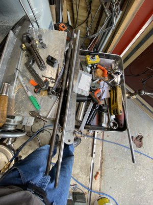
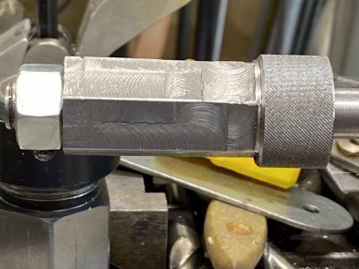
So...I decided to try and use the lathe and thread a few more inches of 7/16”-20 threads. Picked up the threads pretty good....and once I cut about 3” more....I cleaned up with the die. Appears better. I made a mistake of using a scrap piece of 304 stainless for the top nut. Man that stuff is difficult to machine. It work hardens instantly. Anyway I did manage to thread it 1/2”-13.... machine a 7/8” hex in it.....make a centering bushing out of delrin so that the bar is centered when tightened. I then put a regular 1/2”-13 stock nut on it. This way....I can use either a 7/8” wrench or a 3/4” wrench on it. The 7/8” hex machined finish looks like crap. But, it works and is an improvement. So I’m happy.
Attachments
- Joined
- Mar 26, 2018
- Messages
- 8,411
I would love to have that drafting machine. It makes mechanical drawing/drafting a dream.POTD was repairing my Post drafting machine. Yeah, I can read a calendar and know it’s year 2020. . . In my defense, I hadn’t used it for about 30 years, but frankly find “old tech” still has its place on occasion.
For those under 50 who have never seen one of these, mine is a Post/Mutoh drafting machine. The base is fixed to the drawing table. There are two swing arms with a pulley in between the two, plus pulleys on either end of the swing arms. The drafting detail (sorry, the proper name escapes me) has an infinitely adjustable base (in rotation) that can be locked into an angular position. Once locked in place, you can move the drafting head around the table and the X/Y scales stay parallel to your work. There’s a push button on the head that lets the scale rotate and lock into other angles in 15 deg. increments.
So, draw a base line on the X-axis and need to draw a 45 angle, push the button and swing the head to a 45, release the button and the head locks at that angle. There’s a protractor on the base with minutes graduations so you can read or draw angles in between.
When I work from an existing drawing, I tape it to the table and rotate the head until the bottom or side scale line up with the appropriate line, then lock the angle of the head. I have scales in fractional inches, millimeters and decimal inches.
I was going to use the drafting machine to dimension a computer scan of a part and discovered one of the pulley bands was snapped. The two arms have tensioning rods so the bands can be tightened on the pulleys. If they slip, you lose angular position. My guess is the bands are stainless and looked to be silver soldered together.
Busted band doesn't run too well on the pulley. . .
View attachment 326535
Looking at the other band, looked to be silver soldered together
View attachment 326536
My fix was to spot weld the band. My spot welder is plugged into a foot pedal so weld time is controlled by the tap time of my foot. I can’t adjust current, only weld time. Well, a tap of the foot for under a half-second blew through the band. I was able to get some really quick taps of the foot to weld around the big hole I made, so it’s holding for now. Cleaned up the inside surface with a Scotchbrite wheel.
Yeah, not my best spot weld. Hit a few more around the hole and it's holding fine
View attachment 326537
The tensioning is done with a steel rod with a bolt on one end. The bolt head has a keyway cut, to tighten the band you stick a nail or small Allen wrench through a hole in the base casting into the keyway, then turn the rod to unscrew the bolt.
The steel rod and bolt are used to tension the pulley band
View attachment 326538
Slip the band over the pulleys and turn the white knob to unscrew the bolt to tighten the band
View attachment 326539
Use an Allen wrench in the base to catch the key way in the bolt so it didn't turn with the rod
View attachment 326540
Works great again and works really well for me getting quick dimensions off an existing part. Pictures here are of a 4x scale Erector set part. I flattened an original part and scanned it on our computer, then scaled up in Photoshop for the hardcopy. I’ve got another thread showing the Erector set part I was making.
Yes, I know it's ancient technology, but I got the dimensions for this drawing in about 15 minutes. I'm accurate to about 0.010" which was "close enough" for my project. Still need to learn Fusion 360 or Solidworks one of these days. . .
View attachment 326541
View attachment 326542
Thanks for looking,
Bruce
- Joined
- Mar 17, 2018
- Messages
- 1,400
Today, I did something that I said that I would never do again.

What a mess I had after turning only 2 rotors.
What a mess I had after turning only 2 rotors.
- Joined
- Jan 31, 2016
- Messages
- 11,477
Making up a few more handles tonight for work . Nothing big . Ream to .626 , broach a 3/16" keyway and drill and tap 1/4-20 set screw holes . ( fill in work makes the night go faster ) 
- Joined
- Jul 14, 2017
- Messages
- 2,448
Today, I did something that I said that I would never do again.
What a mess I had after turning only 2 rotors.
What RPM did you turn the rotors, looks like your speed was too high, cast iron makes a mess but not that much

- Joined
- Mar 17, 2018
- Messages
- 1,400
400 rpm, I really had to hunt for the right speed. I finally found an insert tool with the right cutter. That made all the difference.What RPM did you turn the rotors, looks like your speed was too high, cast iron makes a mess but not that much
GoceKU, I have seen you cutting rotors on several occasions. What setup works for you?
Thanks.