2020 POTD Thread Archive

I run them slow, 63 rpm with carbide insert tools, i often use an old insert because first couple of cuts destroys the insert, suffice finish needs to be even, it doesn't need to be smooth as glass, the brake pads will do the smoothing.
 
Today, I did something that I said that I would never do again.
View attachment 326599
What a mess I had after turning only 2 rotors.
Yeah...I spent half my life with the only lathe I touched was brake lathes. They are just different animals. After closing my shop....the wheels started turning in my head. “I’d convert one of my brake lathes to a general use lathe. The more I read up and learned about machine tools and lathes....I realized that this was a crazy idea. I sold both of them.
They are just totally different beasts. And FWIW....personally I don’t think I’ll ever mount a vehicle rotor on any of my lathes. The mounting accessories of a brake lathe make it a piece of cake to turn a rotor or drum. None of the accessories are in my tool box.
If I have a warped rotor...I usually just buy a new one. Otherwise I hit the rotor with sandpaper and throw new pads on the vehicle.

by the way....check out the prices of rotors on EBay. They are insanely cheap. Like 20.00 a piece for many vehicles. That’s cheaper than paying to turn a rotor. And the old ones make nice bases for tool stands.
 
Last edited:
I run them slow, 63 rpm with carbide insert tools, i often use an old insert because first couple of cuts destroys the insert, suffice finish needs to be even, it doesn't need to be smooth as glass, the brake pads will do the smoothing.
Thanks! I wish that I had tried it that slow. The slowest speed that I tried was about 250rpm. At one point when all the good was worn off of the insert my lathe was struggling to maintain speed. Thats when I turned the insert for a fresh edge and got an amazing finish.

Yeah...I spent half my life with the only lathe I touched was brake lathes. They are just different animals. After closing my shop....the wheels started turning in my head. “I’d convert one of my brake lathes to a general use lathe. The more I read up and learned about machine tools and lathes....I realized that this was a crazy idea. I sold both of them.
They are just totally different beasts. And FWIW....personally I don’t think I’ll ever mount a vehicle rotor on any of my lathes. The mounting accessories of a brake lathe make it a piece of cake to turn a rotor or drum. None of the accessories are in my tool box.
If I have a warped rotor...I usually just buy a new one. Otherwise I hit the rotor with sandpaper and throw new pads on the vehicle.

by the way....check out the prices of rotors on EBay. They are insanely cheap. Like 20.00 a piece for many vehicles. That’s cheaper than paying to turn a rotor. And the old ones make nice bases for tool stands.
I like to say to my boss that you can fix anything, it just takes time, money, and brains. These days I have much more time than money.
I guess knowing what a mess this was going to make before I even touched my lathe, rather than being surprised by the mess, made it not quite as bad. Today is shop vac day after I put my car back together.
 
I made a steel box to fit a Priority Mail flat-rate box, to facilitate shipping pottery from my mom, who has a studio at home
0f7d833dba18d5b44f0cf2950c205afb.jpg

in Hawaii.
b66878637a27ae6fad9ecb6c5e87346f.jpg
 
POTD was repairing my Post drafting machine. Yeah, I can read a calendar and know it’s year 2020. . . In my defense, I hadn’t used it for about 30 years, but frankly find “old tech” still has its place on occasion.

For those under 50 who have never seen one of these, mine is a Post/Mutoh drafting machine. The base is fixed to the drawing table. There are two swing arms with a pulley in between the two, plus pulleys on either end of the swing arms. The drafting detail (sorry, the proper name escapes me) has an infinitely adjustable base (in rotation) that can be locked into an angular position. Once locked in place, you can move the drafting head around the table and the X/Y scales stay parallel to your work. There’s a push button on the head that lets the scale rotate and lock into other angles in 15 deg. increments.

So, draw a base line on the X-axis and need to draw a 45 angle, push the button and swing the head to a 45, release the button and the head locks at that angle. There’s a protractor on the base with minutes graduations so you can read or draw angles in between.

When I work from an existing drawing, I tape it to the table and rotate the head until the bottom or side scale line up with the appropriate line, then lock the angle of the head. I have scales in fractional inches, millimeters and decimal inches.

I was going to use the drafting machine to dimension a computer scan of a part and discovered one of the pulley bands was snapped. The two arms have tensioning rods so the bands can be tightened on the pulleys. If they slip, you lose angular position. My guess is the bands are stainless and looked to be silver soldered together.


Busted band doesn't run too well on the pulley. . .
View attachment 326535
Looking at the other band, looked to be silver soldered together
View attachment 326536


My fix was to spot weld the band. My spot welder is plugged into a foot pedal so weld time is controlled by the tap time of my foot. I can’t adjust current, only weld time. Well, a tap of the foot for under a half-second blew through the band. I was able to get some really quick taps of the foot to weld around the big hole I made, so it’s holding for now. Cleaned up the inside surface with a Scotchbrite wheel.


Yeah, not my best spot weld. Hit a few more around the hole and it's holding fine
View attachment 326537


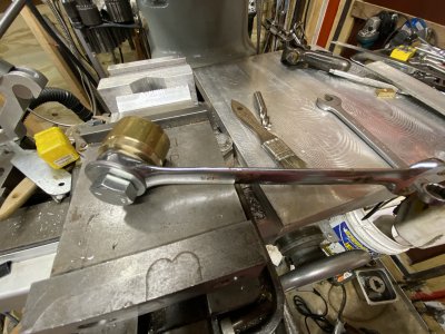
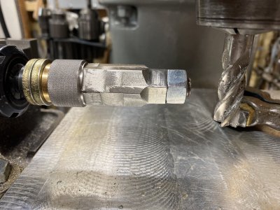
The tensioning is done with a steel rod with a bolt on one end. The bolt head has a keyway cut, to tighten the band you stick a nail or small Allen wrench through a hole in the base casting into the keyway, then turn the rod to unscrew the bolt.


The steel rod and bolt are used to tension the pulley band
View attachment 326538

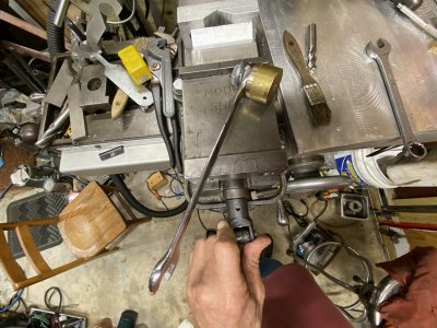
Slip the band over the pulleys and turn the white knob to unscrew the bolt to tighten the band
View attachment 326539

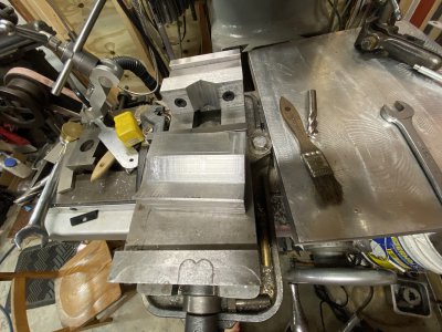
Use an Allen wrench in the base to catch the key way in the bolt so it didn't turn with the rod
View attachment 326540


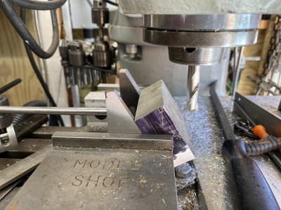
Works great again and works really well for me getting quick dimensions off an existing part. Pictures here are of a 4x scale Erector set part. I flattened an original part and scanned it on our computer, then scaled up in Photoshop for the hardcopy. I’ve got another thread showing the Erector set part I was making.


Yes, I know it's ancient technology, but I got the dimensions for this drawing in about 15 minutes. I'm accurate to about 0.010" which was "close enough" for my project. Still need to learn Fusion 360 or Solidworks one of these days. . .
View attachment 326541
View attachment 326542


Thanks for looking,

Bruce


My dad and/or uncle might still have one of those, both were engineers at Boeing/Rockwell. Very neat tool.
 
I made a steel box to fit a Priority Mail flat-rate box, to facilitate shipping pottery from my mom, who has a studio at home
in Hawaii.

Nice Box.
I'm wondering about the logistics of using it.
I just can't get my head around sending an (almost) empty box back to HI.
I guess it makes good sense if you have items that she wants from the mainland.
You send her stuff, she sends you pottery?
 
POTD was brush-hogging trails on our property and using a finish mower to do around an acre. I use a Massey Ferguson 35 tractor for the cutting. Hopped on the tractor, keyed it up, went to pull on the choke before hitting the starter and no knob on the choke. Must have vibrated off the last time I mowed. Thread checked at a 10-32, so easy to make a replacement.


My circa 1965 Massey 35 tractor
20200607_131132.jpg

Well, there used to be a plastic knob on the choke. . .
20200607_131159.jpg


Chucked up a piece of 5/8" aluminum. Faced, center drilled, tap drilled, tapped and turned the surface down to 5/16". Knurled what would be the perimeter of the knob with a Rockwin hand-knurler. I think the old knob had straight knurls on it; this Rockwin is my only straight knurler. Parted, flipped in a different collet on the 5/16" portion to face the parted surface.


Pretty basic lathe operations: face, center drill, tap drill, tap, turn to diameter, knurl, part, flip and face
20200607_132823.jpg20200607_132859.jpg

20200607_133021.jpg20200607_133308.jpg

20200607_134054.jpg20200607_134244.jpg

20200607_134415.jpg20200607_134737.jpg


New knob in place
20200607_135013.jpg


The original knob was plastic. On the plus side I might be able to find the aluminum one with a metal detector if it falls off again!

Thanks for looking,

Bruce
 
I'm wondering about the logistics of using it.
It seems cumbersome but it's a pain to protect pottery and this will allow us to reuse packing material while preventing damage. Shipping to/from Hawaii is pretty expensive by other means (I live on the east coast); USPS Priority Mail stands out, even paying for both ways. Like you say - my parents often need things that would incur large shipping charges so I think this will come in pretty handy. It was worth the experience anyway. I'd like to be able to make drawer boxes, so it was an experiment working with 14ga sheet. I just hand plasma cut the rectangles, sanded them, and hit the MIG. I'd like to have a brake and have some large angle with which to build it, but keep thinking it's worth making my design a finger brake, so I haven't started...
 
Just a couple of hacks.
Got tired of always looking for a hammer to tap loose my draw-bar after I loosen it with the wrench. I looked in my toolbox and I have a large excess of 3/4” wrenches so that’s going to be the main one. The draw bar is 7/8” and not my favorite size. Kind of a big wrench just for a draw bar. So... I made a hammer by attaching a brass drop off to the box end side of a crap 3/4” wrench.


The other thing I made is a 120 degree angle block for the milling vise to give me a better bite of the ER25 hex chuck. While writing this....it just occurred to me I should have used my square ER25 chuck. Oh well....so what. Now I have an angle block for whatever

Little edit... just noticed that I left a picture out. Since I went with 3/4”....I milled down part of the 7/8” hex I originally cut on the head of the drawbar. FWIW I also side cut the 304 stainless this time. I really should have known better than trying to use the tip of the end mill. The finish is much better. I had screwed a 3/4 sized nut which is 1/2-13 threads and Loctited it on with the red Loctite. But just in case it were to loosen....now the main nut is also 3/4”
 

Attachments

  • FE260AF4-DE92-4DA5-B187-7ABE5AECE2DA.jpeg
    FE260AF4-DE92-4DA5-B187-7ABE5AECE2DA.jpeg
    3.4 MB · Views: 80
  • 02879D40-FAFB-4D7A-9653-8E4D61D457D8.jpeg
    02879D40-FAFB-4D7A-9653-8E4D61D457D8.jpeg
    3.4 MB · Views: 79
  • F527B0CC-4353-4469-A015-E7A443C4322E.jpeg
    F527B0CC-4353-4469-A015-E7A443C4322E.jpeg
    735 KB · Views: 73
  • C79BD06F-8BD2-4892-8A99-64ABD7F7B4DE.jpeg
    C79BD06F-8BD2-4892-8A99-64ABD7F7B4DE.jpeg
    3.8 MB · Views: 73
  • FC9E5233-4B92-4474-BE20-8BB0E010713D.jpeg
    FC9E5233-4B92-4474-BE20-8BB0E010713D.jpeg
    1.8 MB · Views: 82
  • 5CE6E6F5-2E99-4834-A34B-AD0FBA00D4E4.jpeg
    5CE6E6F5-2E99-4834-A34B-AD0FBA00D4E4.jpeg
    824.6 KB · Views: 59
Last edited:
Got tired of always looking for a hammer to tap loose my draw-bar after I loosen it with the wrench. I looked in my toolbox and I have a large excess of 3/4” wrenches so that’s going to be the main one. The draw bar is 7/8” and not my favorite size. Kind of a big wrench just for a draw bar. So... I made a hammer by attaching a brass drop off to the box end side of a crap 3/4” wrench.


A simple and quite elegant idea. I think when I make myself one, I'll cut down one end and cast a lead head on it. Ya never know, it might be needed elsewhere sometime.

.
 
Back
Top