An Electronic Lead Screw controller using a Teensy 4.1

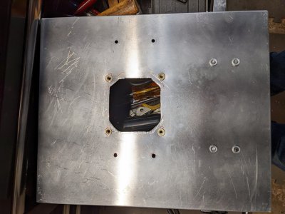
Hacked out holes for the fan intake and exhaust. Got the fan filter guards installed on both the cover and the back of the box. Used my recently aquired rivnut gun to set the M4 rivnuts for the grill guard. Got everything wired up, save for the LED and did a smoke test. Forgot to put in the stepper cables and the alarm light was blinking. Turned off the main power and plugged in those cables and after turning on the power things are ok. The 4A fuse on the 110V side didn't blow, due to inrush, so that's a relief. Also the lit mains switch was working, so that's a plus. Was a productive day in the shop - at least something tangible was done! Forgot to take a picture of the mounted fan grills, but they're not much to look at...
 

Attachments

  • PXL_20221021_192037308.jpg
    PXL_20221021_192037308.jpg
    466.1 KB · Views: 6
Finally got around to populating the PCBWay PCB. Building a board up gives me a chance to see what I'd do different. The PCBWay board was a lead-free board, and I did have to pay a premium for the privelege. Seems to be about the same as the JLCPCB - which is good, since they did come from the same gerbers. Soldering with lead-free is a pain, since the melting point of the solder is a lot higher than Sn63Pb37. But got it all soldered and programmed the board. Tried some machined pin sockets for the Teensy. Thought they'd be lower profile, and they are, but I don't think it was worth the effort. Think I will rework one of the JLC's and chop off the socket and remove it, and solder the Teensy to the board with low temp solder. I need to reduce the height of the Teensy stack, so that it is away from the display. The display will be sticking through a hole the box cover. If the Teensy is too elevated, the pins will short on the metal cover, or the USB cable will foul the cover. Neither is a good thing.

Once powered on, this PCB came right up, so as far as I am concerned, the board is fine.
 
Looks like it's coming along nice. Can't wait to see the completed project.

re: Encoders. I tried some of the Omron Ebay encoders, just for kicks. The first one out of the box had loose screws in it! The screws were rattling around. I'll maintain that these are counterfeit parts. Especially after having to fix one right out of the box!
 
Can't wait to see the completed project.
Me too!

Motor controller box is almost done. Got rid of the cable glands and installed connectors. Was able to find a 4 pin power connector for the stepper and a 6 pin GX16-6 for the stepper encoder. Waiting on some heat shrink so I can finish it up, and finally wire in the power LED.

Hope to make some headway on the display box in the next couple of days. Have roughly located the display on the cover (and ensured it would actually fit in the box without interference. Going to be an interesting layout and milling task.

The only loose screws I have are the one's I put in. As a matter of fact they are the one's holding the rotary encoder to the encoder plate. Got to take it apart and maybe loctite them. They seem to be backing out.
 
Had a few interruptions today, but finally figured out the dimensions for the Display Cover Plate. It turns out I made my life harder than necessary by my PCB dimensions and hole spacing. Lets just say the two of the holes were in a bad place. So I need to make some offset spacer blocks. Was tricky to get everything to fix in the box. Not something I am very good at.

My heatshrink tubing came in today. Will try to tidy up some of the wiring tomorrow, and finally start to cut metal on the die cast aluminum box.
 

Attachments

  • ELSDisplayCoverPlate.pdf
    226.6 KB · Views: 4
  • ELSPCBSpacerBlocks.pdf
    206.4 KB · Views: 5
Think I put holes in the die cast box cover where I shouldn't have this afternoon.:( I just walked away from it, because I didn't want to make the cover worse today. Maybe tomorrow I can figure out what I did and maybe find a way to save it. If it is not saveable, I'll see if I can make a cover plate of my own for it. Or I will cave in and buy a new box. Drat.

The laser printer crapped out today. I hope it is just that we ran out of toner. Can't complain really, since the cartridge lasted 4 years. Unfortunately, I was thinking about the toner, instead of correctly reading the drawings by my mill...

I don't recall if you have a DRO on your mill. Both of mine do and I find it useful to use ordinate dimensioning on my working drawings. My zeroes are set at my work reference zero so when my DRO coordinates match the dimensions on the drawing, I'm good to go. It saves me from making a lot of stupid mistakes.
 
I don't recall if you have a DRO on your mill. Both of mine do and I find it useful to use ordinate dimensioning on my working drawings. My zeroes are set at my work reference zero so when my DRO coordinates match the dimensions on the drawing, I'm good to go. It saves me from making a lot of stupid mistakes.
Yes, I have a DRO on my mill. I should have dimensioned my drawing from my 0,0 datum. But I didn't. And then I just plain misread my drawing. I will update the drawing in CAD, but will also have to copy it to the paper drawing by hand, as I don't have a working printer. Ordered a new toner cartridge.
 
Decided to work on something a little different and finished the motor control box. Wired in the LED that shows the motor power is up. I can put the cover on the box. But I should leave it off so I can attach it to the lathe stand. Probably use some rivnuts in the stand.

Next, I made four twisted pairs of wires using my bench vise and an electric drill on slow. It's an easy way to make these. The four pairs were then soldered into GX16-9 female cable connectors. With this cable, my ELS functions again, since I can connect up all the controls and feedback.

To celebrate, I did a quick lathe project to make a razor stand out of 304 stainless. Used the fine feed for turning the diameter, and for boring. I drilled out the hole to 15/32" and bored it to 0.500" which is a few thousandths larger than the razor handle. It's a good, but not tight fit. Came out ok for an impromptu project.
PXL_20221026_205023993.jpg
 

Attachments

  • PXL_20221026_223309799.jpg
    PXL_20221026_223309799.jpg
    310 KB · Views: 8
Mounting the motor box to the lathe frame is trickier than I thought it would be. Another of these, need a long skinny drill, deals. Guess I will have to modify what I was going to do.

I was going to mount with 4mm rivnuts. The idea was to 1) clamp the box to the frame, 2) use a 4mm drill through the box into the frame which is hollow square tubing. 3) Then remove box, and drill the holes to the correct rivnut size, and install the rivnut.

I don't have a long 4mm drill, but I do have a longer 5mm drill and I think a long 1/4" drill. So I will up size the hardware a little. The drill will reach, but there is a box flange in the way that will interfere with the drill chuck. So I need a longer drill (or drill extension) to move the chuck away from the box flange. If all of that doesn't pan out, I will mount some angles on the lathe stand and then attach the control box to the angles.
 
Back
Top