An Electronic Lead Screw controller using a Teensy 4.1

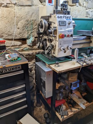
Went with 5mm rivnuts. Got two of them in, enough to hold up the box. Used the technique in the previous post, and drilled through the box and straight into the lathe stand. Then I removed the box and drilled out the holes in the stand to the correct size. That was a M drill. One of the rivnuts needed a little pursuation to insert, but managed to do it. I seem to not to know when to stop pulling on the rivnut. Managed to pull out the threads of one! So I had to drill it out and put in a new one. Wasn't hard to do. Need to install a third rivnut, but that will be for another day. The rivnuts are in an inverted L pattern.

With the box mounted, it is starting to look like I meant it, rather than a total mess. It all powered up and nothing exploded, so that is good.
PXL_20221028_213344273.jpgPXL_20221028_213411201.jpg
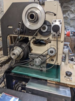
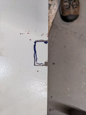
Started looking at the cover to the pulleys and former gear chain. It turns out the very bottom of the cover fouls with the stepper motor pulley. I marked it and will cut out a notch in the cover. I will probably make a little sheet metal guard over it all. Lord knows how I can do that, but somehow I will muddle through that. I need to make some other cutouts for the cables, but I think that won't be too hard. I will use cutoff disks to cut the metal, it is steel and too thick for my hand nibbler to get through. If I really squeeze hard I can cut off a piece, but it is too tough to use continually. If I had a power nibbler, that would be different. The cable holders I got are just a little bit loose. They allow the cable to slip. While great for adjustment, it is not good for vibration. So I will have to wrap the cable with something so the rubber will grab it.
PXL_20221028_213531951.jpg
I will get back to the display box in a couple of days. It was frustrating me so much, that I needed to avoid it awhile.
 
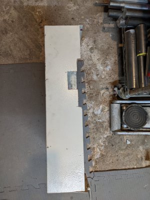
Kind of got the hang of this sheet metal cutting after a bit. After breaking a few of those brittle Dremel disks I found a fiberglass reinforced one. Make it a lot easier to cut the steel. Notched out an opening for the pulley and the motor mount block.
PXL_20221101_193533606.jpg
After all this, tried to mount up the cover. Discovered that it would be pretty hard to do with the current shop set up. Lathe is too close to the wall at the moment. And I have a bench that is too close to the lathe to easily swing open the cover. I knew about the bench, but had forgotten about the distance to the wall. Aha, it is all coming back now... Maybe if I move the bench (and the hundreds of pounds of tools) I can just access the screws. With the ELS, it would be rare to have to open the cover. I don't have to change gears anymore.
 
Got interrupted by, fall chores aka raking leaves. This year decided to use my mower to bag up leaves. This partially chops up the leaves. I then dumped the chopped up leaves into my vegetable garden beds. Worked well last year on a sample bed, so decided to do them all.

While waiting for the leaf blower battery to top up, I grabbed a marked up drawing and went down into the shop. After a couple of minutes, I pretty much convinced myself that indeed I did drill the holes in the display box wrong. I got the holes half a diameter off. So I will make my own cover. It won't be as nice as the original, but that's how the cookie crumbles. I found a piece of 1/8" x 6" aluminum stock and cut it to 6-3/4" long. Once I true the ends to 6-1/2", I need to cut it to 5" wide. That's for tomorrow. I hope to get most of the features in before going away for the weekend. My youngest daughter just got engaged, so we want to go visit her.
 
Back home. Had a great weekend. Finally got my printer to work (new toner) and updated the drawing so that everything references the 0,0 datum.

Well, I just found out a problem with my DRO. It is dropping counts :mad:. I was wondering why in the past few projects why I was having trouble. I was drilling holes and thought I noticed that the position was off in X. I went back to the datum 0,0 and found it had shifted, a lot, like 5mm over 165mm. Previously when that happened, I thought it may have been the work piece moving, which I have seen before. Now I think this DRO issue has been happening for a while. So it looks like I buggered up another cover plate. :( I'm 0 for 2 on this part. And that is after only two holes!

Guess I have to pull off the x-axis scale from the mill and see what is happening. Maybe it is swarf, or a loose fastener... Dang, not the fun way to make progress.
 
Guess I have to pull off the x-axis scale from the mill and see what is happening. Maybe it is swarf, or a loose fastener... Dang, not the fun way to make progress.
Bummer. Is this scale a stick on magnetic scale, or optical scale?

We did have an Heidenhain optical scale become 'jumpy' at work. Pulled it off the machine, and washed/wiped the glass down with alcohol, and cleaned the read head and it was back up and running. Fortunately the CNC controller threw a fault, so nothing was scrapped...

Good luck!
Appears to be an optical scale. Hoping it won't be a big deal. Kind of surprised at how it manifested itself. Took me a couple of incorrectly made parts to find the problem. Glad I found it though, so I can fix it, rather than scrapping parts.
 
Appears to be an optical scale. Hoping it won't be a big deal. Kind of surprised at how it manifested itself. Took me a couple of incorrectly made parts to find the problem. Glad I found it though, so I can fix it, rather than scrapping parts.
If it's optical, a good cleaning may do the trick. Q-tips and alcohol will be your friend there! Not sure how they can get dirt and oil in them. Gravity should keep everything out, but somehow it seems to work it's way in.
 
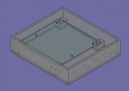
Well, since I got a 3D printer, I decided to design an enclosure for my display. Did the design work in FreeCAD, and exported the stl. Then imported into PrusaSlicer and made some gcode. I am printing a draft of the box. I expect it to be NFG. That's ok, there's a lot to learn. I hope at least the PCB lines up and I can fit in the GX connectors. I will know more by bed time. This is the draft box - there's a lot more work to do.
isoview_teensydisplaybox.jpg
 
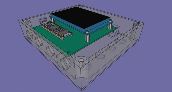
Printing Rev B of the box. Added stuff to hold the lid down, a rectangular hole in the side of the box for the USB connector, and pockets for magnets to hold it down to the headstock. 3d printing is time consuming, ie, it's slow. This box will take 8 hours to print. Hope there aren't too many revisions at this point. It sure is good practice with CAD.
assemblyisoperspective.jpg
 
Everything printed fine, which is a relief. Too bad reality was not as kind. Mounting holes are correct, bosses have enough room for the board to seat. But the USB port does not line up with the cutout in the wall. It's way off, about 2mm, even though my assembly model shows everything is perfectly aligned. Seems I have an error in the PCB model, and some of the bodies in the model are not located where the model says they are. Time to dig into this. Multiple piece assemblies are unforgiving. Rev C, here we come.

I made several mistakes with the PCB FreeCAD model. Fixed all that up, to the best of my knowledge, using physical measurements on the PCB and cross checking with KiCAD measurements. Then I went back to A2plus (assembly view) and saw that the re-imported model, looked like what I had. That being the cutout was not in the correct place, the model showed what I saw physically on the RevB box and the PCB. Then the cutout position was iterated until the cutout dimensions were correctly and symmetrically about the USB connector.

I need to review the magnet pockets. The horizontal widths are ok, but the vertical width is shy of 12mm, probably due to flat spotting. Going to print the existing magnet pockets, but flat to test the adhesion to steel with the existing gaps. Should give me an idea. Only have 2 magnets, more are coming in, but it will give me a qualitative feeling.
 
Back
Top