An Electronic Lead Screw controller using a Teensy 4.1

Know that feeling all too well. I ended up with that situation on my X axis - it was a touch short and also 5um instead of 1um. As you know, i ended up purchasing a second scale the correct size to replace the X axis scale. However I ended up with a 570mm travel, 660mm hole spacing and 676mm total length scale for my Z axis. The scale has more travel than needed but easily fit into the space and in fact sits nicely on the cast webbing with minimal spacers so i left it long - maybe you'll get lucky and be able to do the same. The brackets that came with my Sino scale were a bit mickey mouse but i was able to make them work - they are universal in the most broadest of terms.

Glad to hear that you got the X axis mounted. That should be the most challenging one - are you rolling with the 3D printed mount or are you going to mill it from Aluminum?
Sticking with the printed X read head holder for now. If I run into issues, I'll fab it in aluminum. It holds the read head quite snugly against the saddle, and will protect the read head if it gets hit.

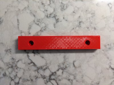
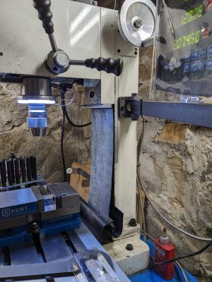
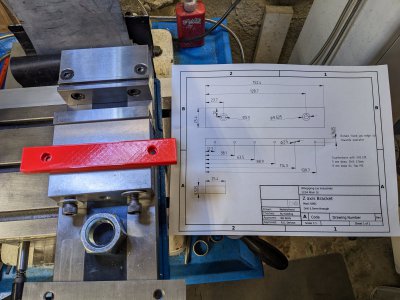
I'm printing a prototype curtain holder for my mill right now. That one will end up made of aluminum. I'm not sure I got the hole spacing right. A while back I basically wrecked the Z accordian. I didn't like it anyways, as the bottom piece was limiting Y travel. The piece will be just a 3/8 x 1 x 6 inch chunk of aluminum clamping some rubber sheet to the mill head. Getting the screw hole locations right while looking underneath the head, well that was a bit of guesswork, which is why I will print it. This is a simple print, so I can confirm fit. I already have milled the piece to length, just waiting for the holes. If I had some transfer screws of the right size, I would have used them. The screws are a weird size. I think they are M5, but a new M5 screw doesn't screw in the hole. They measure 4.76 mm, which is right about what a 10-32 mic's at. Since the screw is so short, it's hard to measure the thread. 0.8mm fits, which is correct for M5. Guess I will clean out the crud from the hole, and do an M5 fit check again. If it doesn't quite fit, I will tap the hole to M5.

Not quite sure how I will mount up the Z scale on the lathe just yet, but I will slowly cobble something together. At the moment I'm having a little bit of trouble visualizing it. I understand the basic idea, but implementing it on my lathe is tripping me up. If I had better access to the back, it would probably be a lot easier. I will print a couple of things to get in the ball park, then do aluminum from there. I'm envisioning some ghastly initial contraption with too many degrees of freedom and somehow reducing most of them, so that removal (for any reason) isn't a nightmare.
 
Got the printed prototype for the mill done and tested. Came out good the first time. Good enough to make one from aluminum. Having the broken Z accordion has been hard to look at. Especially when making parts for the lathe. I'll make an aluminum version tomorrow.
PXL_20230412_214943259.jpg
 
For once, this went easy! Made the piece out of aluminum. Used some rubber cement to glue the thin rubber sheet to the aluminum. Clamped it for about 90 minutes in a vise. Then used a 5.5 mm transfer punch to cut through the rubber sheet for the screw hole. Since the hole was drilled to 5.5 mm, the punch cleanly sheared the rubber sheet around the screw hole. This worked a lot nicer than trying to cut the rubber with a razor blade. I left the rubber a little long in case I have to clamp it some more on the front edge. Then I installed the aluminum piece to the mill. Here it is.
PXL_20230413_165034013.jpg
One of those silly little jobs that you don't want to bother with, but should be done. A round tuit. I left the rubber long on the bottom as well. Will end up cutting it to length eventually, once I convince myself of the correct length. The block is fastened using 2 M5 SHC screws to the mill head in existing holes. Had to tap/chase the holes in the mill - they were full of a ton of grit.
PXL_20230413_165202751.jpg
Didn't drill and tap the 6 M3 screws, deciding if I really need to clamp the front edge at all. After all, the 1" x 6" face is clamping the rubber to the mill. (And the rubber is glued to the aluminum.)
 
Good idea.
A roller blind leaps to mind on dealing with the excess.
 
Good idea.
A roller blind leaps to mind on dealing with the excess.
I tried the roller blind idea using a piece of PVC pipe, but had too much friction due to the spring expanding inside the pipe. Gutted an old blind, which was an adventure, but was stymied by the spring expansion during the wind up. Might revisit the idea, because it would be pretty cool. Would use a threaded metal tube or pipe with end caps to contain the spring within. Now it could have been that I cut the spring too long or short, after all, it started out as a 30" wide blind. Have no idea what the optimal spring length would be for a 6 inch wide roller. But it does have to allow quite a few turns.
 
I tried the roller blind idea using a piece of PVC pipe, but had too much friction due to the spring expanding inside the pipe. Gutted an old blind, which was an adventure, but was stymied by the spring expansion during the wind up. Might revisit the idea, because it would be pretty cool. Would use a threaded metal tube or pipe with end caps to contain the spring within. Now it could have been that I cut the spring too long or short, after all, it started out as a 30" wide blind. Have no idea what the optimal spring length would be for a 6 inch wide roller. But it does have to allow quite a few turns.
Right, the width would be a challenge for spring wind-up. Hmmm....
 
Converted the DB9 connector on the X scale to a GX12-4. On the slim scale that I have, there is a ferrule that seems to be clamped to the end of the stainless jacket to the cable. What a pain in the neck it is. For the moment, I have wrapped some (TIG) steel wire around the ferrule and to the GX12-4 connector housing to keep the jacket from riding up on the cable. It's hokey, but it does work. Need to come up with a way to terminate the corrugated stainless jacket better. Probably should have used some heat shrink, but I didn't think of that. Maybe some self vulcanizing rubber tape would work. Anyways, the X scale is in and reading out on my X axis! I will have to calibrate it at some point. It doesn't quite match the dial, but who knows how accurate the dial is on a G0752Z/G0602? On the dial there is a label which says: 0.025mm = 0.001", which isn't quite true... So I am not quite sure how the dial is really set up. However, the DRO reads out pretty close, at least for 0.010". So one axis is done. Still waiting on the Z axis to arrive.

Just to document it: The KA500 DB9 pinout is
Code:
1    NC
2    Sig Gnd
3    NC
4    NC
5    NC
6    A
7    +5V
8    B
9    R
shell    shield
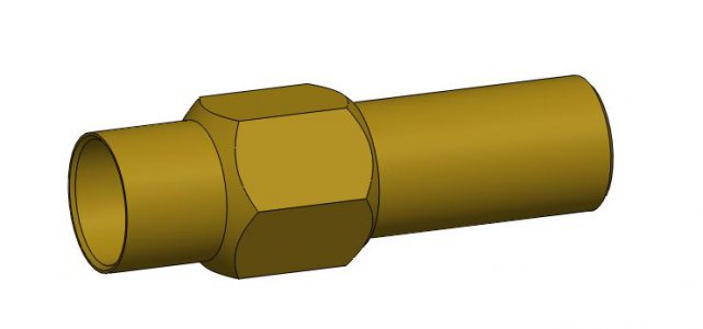
I used brass compression fittings when I added optical homing to my Tormach mill. The fittings needed to be sealed against flood coolant so I ran oil resistant PVC tubing over the flexible stainless. I modified a 5/16" hose nipple by turning the barbs off and turning one end to fit a 5/16" compression fitting x 1/8" npt and the other end was bored to accept the flexible stainless. The stainless was epoxied into the brass fitting and the 5/16' pvc was slid over the stainless and nipple nub for a liquid tight connection.

I didn't need a liquid tight connection on the 602 so I just made up some split clamps to capture the stainless.
The termination I have to do is at the controller end, which doesn't need to be (and isn't) fluid tight. What do these split clamps look like? Are they hinged?
Edit: Looked some up on McMaster. I think I can design something that would work. Whether I could make it - well, let me design it first.
 
Last edited:
The termination I have to do is at the controller end, which doesn't need to be (and isn't) fluid tight. What do these split clamps look like? Are they hinged?
Edit: Looked some up on McMaster. I think I can design something that would work. Whether I could make it - well, let me design it first.
Here is the system that I used on the lathe. https://www.hobby-machinist.com/threads/another-lathe-dro-install.34106/

The system that I used on the mill doesn't need the waterproof feature. It is an elegant way o deal with the terminations. While I used a compression fitting, any number of other options could be used.
Flexible Conduit Termination.JPG
 
Back
Top