An Electronic Lead Screw controller using a Teensy 4.1

Curious to know if the printed version would be solid enough for permanent installation? That part looks like it'll have some challenges to make out of aluminum but not impossible.


I have the same issue with machining... then it's time to start over and try again. Or i get to almost the last step forget what i'm doing, mess up and end up starting over sometimes because my play time is interrupted and not contiguous.
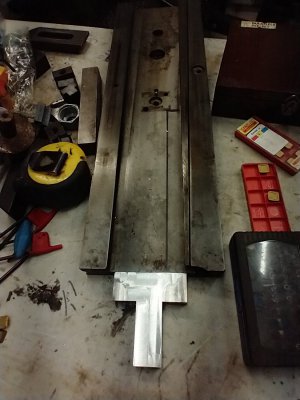
Well, I thought it would be machinable, up until that 1mm wide guide I put in. That would be tricky to machine. But I do think the printed piece would be pretty good. Is it 1um good - that's hard to tell. I bet it might creep after a while. It is pretty stiff relative to crushing the U. Advantage of printing this is I can be doing something else while it is printing. If I screw up, a print costs $0.89. The same piece of aluminum would be about $2. I have just enough aluminum to make one of these. If I mess it up, I do have some 1" steel I could use. A lot harder to machine though, but a lot more rigid than plastic!

I will print version D tomorrow. The version C above just kisses the tail stock ways pyramid. Other than that, the holes line up for the read head, and the U channel width is just right. Version D has a little more clearance for the ways pyramid.

I have yet to drill (and tap) the saddle for this bracket. I may use one of these prints as a drill guide. Not as good as a drill bushing, but it should do the job.
 
If you get into a spot and need some more stock let me know and i'll send you some.
 
Curious to know if the printed version would be solid enough for permanent installation?

I’ve been using a printed “prototype” holding a read head on my mill for several years.
 
After many tries at getting it right and not quite getting the correct channel width, I put the last version of the printed piece in the mill and just widened the channel. I was experimenting with variable layers and not quite getting there.

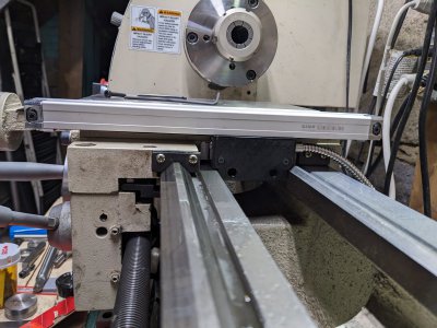
Here's the piece mounted to the read head and scale on the lathe. Now I need to mark the screw locations with a transfer punch, drill and tap.
PXL_20230401_214618247.jpg
 
Well, what a dope! Finally got around to the back side of the lathe, and removed the old 0.001" mag tape DRO. I take my new Z scale and discover it is way too short. Groan. Like over 100 mm short. I don't know what I was thinking when I ordered it. Have to research linear scales again. I had ordered something like 420mm travel, but I actually need about 520mm - 540mm.

Still have to mount the X scale to the saddle. Think I have enough room to drill it if I move the saddle to the tail stock end. I'll see if I can pull that off.

Edit: No I can't. Need an extended length drill to do that. Chuck interferes with the ways.
 
Last edited:
@TorontoBuilder - unfortunately that grizzly lathe doesn't seem to have as much of an ear on the back side like yours or mine does so you have to stick it all the way out the back which really adds to the length needed behind the lathe.

Here's a pic of how i mounted mine on said ear so that it doesn't interfere with the tail stock or the back splash:

View attachment 442722

@WobblyHand - hopefully you take a pic of your milling setup - the cast on these lathes doesn't seem to have any "flat" surfaces. The ear where i mounted the read head was slightly curved but i was able to snug up both screws such that it was level and the read head lines up with the scale so i think it's good.

You've made good progress and i am enjoying following along.

I solved my issue by ditching the glass scale and ordering 2+2 pitch magnetic tape, and a 1 micron resolution read head.

I'm milling a 1.8mm deep slot on the underside of the cross slide and adhering the tape within the slot. The magnetic encoder will mount at the rear with the reader profile facing up towards the underside of the cross slide. I likely had enough room to mount everything with but just to be sure I machined an extension from aluminum to provide 3 more inches of depth to the rear.

IMG_20230406_201321342.jpg

Later today I'll be milling the 10mm wide x 1.8mm deep slot in the underside of the slide, right down the middle. I'll put the cross slide back on the lathe and see how much of the tang I can cut off. I think most of it is unnecessary, except as a good place to affix the wire from the read head to.

Oh and BTW after purchasing my read heads and tape from Ditron on aliexpress I found a fellow in the UK who has developed his own DRO Control box and micro magnetic read heads to provide the most compact installations imaginable. The microDRO outputs to any android device with the TouchDRO app installed.

I'm blown away by this design and will be using it on a future project.

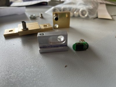
Below is his 8 x 14mm read head, along with various mounts he has made for it. He hadn't yet seen embedded mounting method, which requires a slightly different and much smaller mount. The boards can be had with direct solder connection instead of this rather large looking connector, which is really quite small compared to chinese equivalents.

encoder 2.jpg

Combined with the embedded magnetic tape technique
 
Last edited:
I solved my issue by ditching the glass scale and ordering 2+2 pitch magnetic tape, and a 1 micron resolution read head.
snip>
Oh and BTW after purchasing my read heads and tape from Ditron on aliexpress I found a fellow in the UK who has developed his own DRO Control box and micro magnetic read heads to provide the most compact installations imaginable. The microDRO outputs to any android device with the TouchDRO app installed. snip>

I don't mean to hijack WobblyHand's thread but I'm very interested in the things I highlighted above.
Your project is worthy of it's own thread, for sure. If there is one, please link here.
At any rate, can you post links to the tape and read heads that you purchased.
If the fellow in the UK is posting/selling his development, I'd like to have his contact information also.
Great stuff. Thanks for posting.
yeah I dont want to distract from this thread either so I will post more info here once I get more detailed info
 
Got the X axis installed. The long skinny drill was long enough to allow me to hand drill the X read head bracket mounting holes in the saddle. But because the drill was long, it was hard to get much pressure on the drill bit to have it cut. If you pushed too much the bit would bow! But got it done and the blind holes tapped to M4 using a spiral flute tap. Love those taps.

Now for the Z axis. I'm all over the map with this. Thought I'd measured it right the first time, but ended up with something ridiculously too short. I've measured it with the only thing I have - a tape measure, and I am not that confident of the length. The original factory mag tape could have been longer. I think I will simply buy a glass scale a little oversized and cut to length. I'm 0 for 2 on the scales, so I'd like to get it right this time... So for what seems like the 10th time, I will go downstairs and measure the back of the lathe.

Edit: Done. Ordered a Ditron 1um scale, 531 mm travel length. This should have a 650 mm hole spacing and a 664 mm total length. Should be here in under two weeks. I briefly looked at the mag tap options and didn't see any options that looked significantly better from a mounting perspective. Hope this one is the charm! The Ditron customer rep was up late, and responded immediately to my questions. That was pretty good.
 
Last edited:
Know that feeling all too well. I ended up with that situation on my X axis - it was a touch short and also 5um instead of 1um. As you know, i ended up purchasing a second scale the correct size to replace the X axis scale. However I ended up with a 570mm travel, 660mm hole spacing and 676mm total length scale for my Z axis. The scale has more travel than needed but easily fit into the space and in fact sits nicely on the cast webbing with minimal spacers so i left it long - maybe you'll get lucky and be able to do the same. The brackets that came with my Sino scale were a bit mickey mouse but i was able to make them work - they are universal in the most broadest of terms.

Glad to hear that you got the X axis mounted. That should be the most challenging one - are you rolling with the 3D printed mount or are you going to mill it from Aluminum?
 
Back
Top