An Electronic Lead Screw controller using a Teensy 4.1

I thought that might be true, but wasn't sure. Will need to prop up the apron first, because that's a lot of weight on the lead screw.
The weight isn't that great. Once the saddle is free, you can slide the apron either toward the headstock or the tailstock . You can put a block of wood under the apron for support if you're concerned.
 
It turns out, there's one more screw to undo. I missed it, so I had to slide the saddle off the tail stock end. Once I looked at it, 'twas obvious. And it doesn't appear to be on the parts list. Oh well.

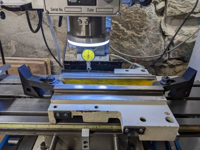
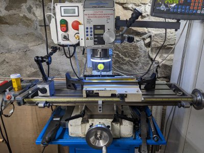
The saddle is off and on my mill table. I put some beer can shims under one end to level the saddle. It is clamped onto my mill table and all lined up. Unfortunately, due to the size of the saddle and my mill, I have to mill on the far side. Not my most favorite thing to do, but it's really no problem.
 
@TorontoBuilder - unfortunately that grizzly lathe doesn't seem to have as much of an ear on the back side like yours or mine does so you have to stick it all the way out the back which really adds to the length needed behind the lathe.

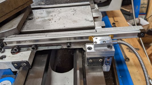
Here's a pic of how i mounted mine on said ear so that it doesn't interfere with the tail stock or the back splash:

PXL_20230328_225227324.jpg

@WobblyHand - hopefully you take a pic of your milling setup - the cast on these lathes doesn't seem to have any "flat" surfaces. The ear where i mounted the read head was slightly curved but i was able to snug up both screws such that it was level and the read head lines up with the scale so i think it's good.

You've made good progress and i am enjoying following along.
 
Had to go out for a while.

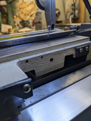
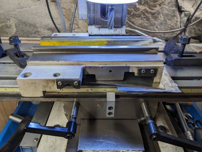
I'll get a picture of the saddle on the mill. Had to shim one end to get it level. At least on the bottom side it's pretty bad. For that matter, the top is kind of rough as well. Ran an indicator along the dovetail in the X axis. It's mostly lined up now, but I will check it again before I run a pass.
PXL_20230329_001953408.jpgPXL_20230329_002015750.jpgPXL_20230329_002039501.jpg
 
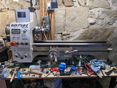
Here's a picture of my lathe now: no tail stock, no saddle. And yes, it's a total mess:faint:
PXL_20230329_002908889.jpg
 
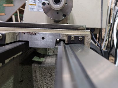
Milled the read head area vertical. Had to take off 1.25mm. Was reluctant to take off more.
PXL_20230329_180530601.jpgPXL_20230329_180225861.jpg
At least there's a quasi flat area now. Used a roughing end mill 1/2" at 680 RPM. Slowly shaved off a little at a time. Hope I did enough. If not, it'll be back on the mill. Now to figure out the spacing for the read head spacer.
 
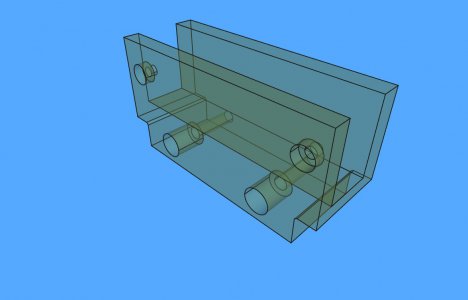
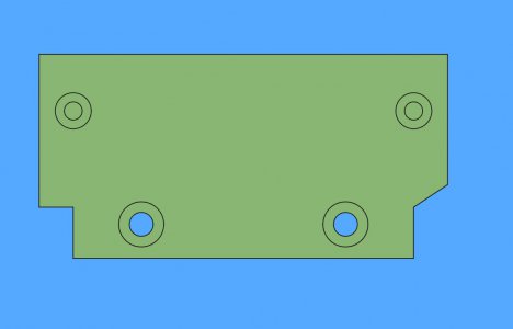
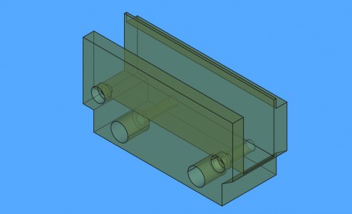
Made some basic measurements. I have a chunk of aluminum that I can make this from. It seems the read head has threaded holes so I will have to have a through hole on my side. This is different than I expected. Here's the idea. It is a combination read head holder and guard. Here is what I have modeled in CAD. Model isn't finished yet, but is the basic idea. The mounting holes for the read head are not correct - simply because I haven't measured this stuff yet. I may print this to see if the concept is way off or not. May sink in a third screw in the back, but I think 2 M4 screws should be good enough. Planning on using M3 to hold the read head to the front side of the U channel.
readhead_bracket.jpg
Front of the channel is 5.1mm thick, rear is 6mm. The M4 screws are deeply counterbored, so I can use the M4x20mm screws that I have. Depth of the block is 25.4mm, width is 72mm at the top and 60mm at the bottom. If I plan it out right, this shouldn't be too hard to make.

Edit: Printed this and found out the right side interferes with the rear prism for the tail stock. So I will cut off the corner a bit, and will reprint and see if I have any other flub ups. The printed piece is surprisingly rigid.
cutoffthecorner.jpg
 
Last edited:
Yeah, well, up to version 3 now. Seems I didn't account for clearance of the aluminum bar behind the scale. Still, I can go through a few tries with this plastic stuff, iterating a couple of times until I get it to be reasonable. This version should have the screw holes lined up for the read head. I am using the M3 holes in the read head rather than the M4, because I don't have enough depth to counter bore the screw heads. The eagle eyed out there may notice the cut out at the top back edge. This is to clear the aluminum bar. I kept the thin edge there to act as a locator to the bottom of the scale. Don't know how well that will work out, but I will print it and do a fit check. If it passes muster, I will try to machine it from some 6061.
versionC.jpg
 
Curious to know if the printed version would be solid enough for permanent installation? That part looks like it'll have some challenges to make out of aluminum but not impossible.

Yeah, well, up to version 3 now. Seems I didn't account for clearance of the aluminum bar behind the scale. Still, I can go through a few tries with this plastic stuff, iterating a couple of times until I get it to be reasonable.

I have the same issue with machining... then it's time to start over and try again. Or i get to almost the last step forget what i'm doing, mess up and end up starting over sometimes because my play time is interrupted and not contiguous.
 
Back
Top