G0704 CNC Conversion (yes, another thread on this :) )

Finishing a few projects while I wait for the rest of the stuff to arrive...

Machine the sides of the 5C to have those side paralelo and also drill holes to make it easier to secure to the table...

IMG_3033.jpg

and this arrived today

448B8A3D-E780-4ABB-8B93-16AAB2E0BAA4.jpeg
6E0FFD03-ED12-4812-8D4C-116CA23BCCB1.jpeg
 
Finishing a few projects while I wait for the rest of the stuff to arrive...

Machine the sides of the 5C, drill holes to make it easier to secure on the table... I ordered a
View attachment 311782

and this arrived today

View attachment 311833
 
Oh, and elongated the hole by 0.100” as recommended by Dave. So this should be done.

Now to find a proper enclosure for the electronics...

F1B33C4D-BD7F-484D-8AFA-84F110E6DFBD.jpeg
 
I just realized that I have been wasting time... I could have started working on the electronics... do not need to wait for the adapters for that... just need an enclosure to house everything in... let me stop by the local shop and see if they have something that I can use.

Special/dedicated enclosure are not cheap! Hope that I can find something second hand in the local Skycraft surplus place...
 
...
If you go the same route I did, then the following information is applicable to you. If not, please ignore it.

I opted for an off the shelf IDC-26 breakout board and ribbon cable. Since it wasn't explicitly designed for the ESS, it required me to add a few pulldown resistors to get the inputs reading correctly. This isn't shown on the drawing here. This isn't an issue with the ESS, but rather the cheap breakout board (there aren't really any good ones for the 3rd port on the market).

The resistors are discussed in post #59. You need a resistor on each dedicated input (10, 11, 12, 13, & 15) of a value between 220 ohms and 1000 ohms. 470 ohm would probably be ideal, I used 220 ohm.
I had missed this... I ordered the IDC-26 breakout board and the ribbon cables. I have plenty of resistors left from other projects.

I also ordered the cable organizers with covers and some of those slotted rails...

I lost the reference to the breaker/protectors... need to find which one to order as well...
 
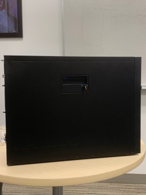
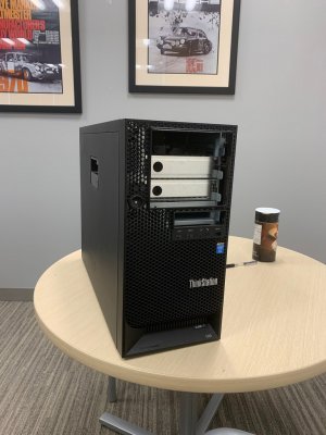
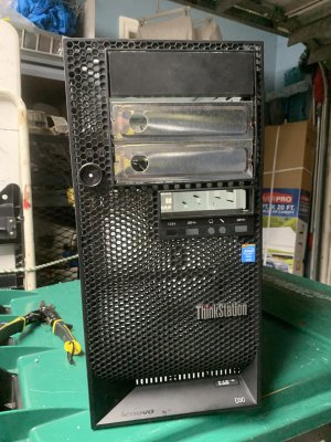
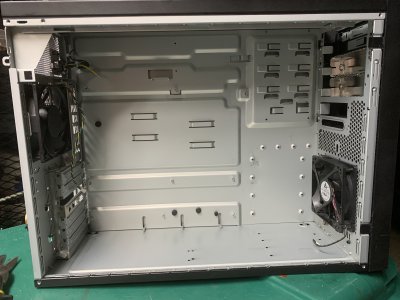
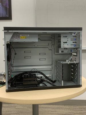
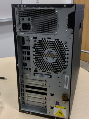
I have a case! Old computer case... stripped down... will remove the rivets on the remaining stuff (where the drives are held in place) that is in there and it will have a completely empty area. Has two fans that will remain in place to keep some air flow.

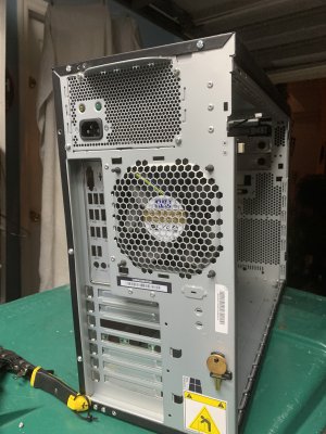
You can see the power supply, but the internals are also gone. I just kept the skeleton to use the rear trim for the power plug. Will modify the rest when I get home. Side cover has a lock with key...can't say that I have seen many cases with that...

This should do just fine, I hope.

IMG_3170.jpg

IMG_3172.jpg
IMG_3171.jpg

IMG_3173.jpg
 
Last edited:
Usually PC cases covers are just bolted down with a few screws... this one was riveted all over in addition to having screws!!! After drilling out the rivets I was able to get the other cover out. With it out of the way, I could get to the rivets holding the internal brackets that held the disk drives...

All removed now.

I also modified the old power supply housing and left just the outside cover with the power plug...

Fans installed.

I will now measure what I have to work with and get a sheet (not sure if to use plexiglass or aluminum) to make the mounting plate.

Outside dimensions for the case : 8”D x 17”H x 22”W

E779525B-2695-4828-A59A-4536B83008BD.jpeg
C11ECA19-6815-4457-B9A5-497A012BE4E9.jpegF9D98732-AE25-4637-B654-FD6999F579FE.jpeg
 
Last edited:
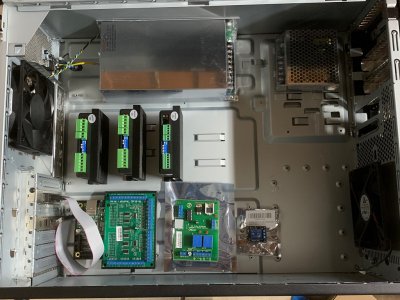
Playing with the layout... Here I thought this case was just right for this... space goes away quickly. Still missing are the rails where the breaker would be... and the wire organizer... And I have to take into account the recommendation of keeping signal wires away from power wires...

I need to play around with this a little bit more... maybe moving the power supplies to the top or bottom... that would free up space on where the rest of the components are mounted... humm... rails and wire organizers arrive tomorrow. I will just wait for those to get here and try again.

The other thing is that I have not seen a wiring diagram with the components that I have... so I need to search and read up a bit more to make sure I got this right.

One thing that I go was a CNC4PC C6 Spindle Speed Control Board... but I do not know if that works with the stock motor or if that is for when I upgrade the motor to one from a treadmill... something else that I got just because I saw another build that had it, but forgot to check what setup it was attached to...

I ordered a 1/4"x24"x24" plexiglass sheet that I will cut to 16"x18" and use as the subpanel.

Learning a lot...

Let me print out a base for those two boards (the CNC4PC C6 and the 5v Relay Module)... At least I can do that tonight.

IMG_3179.jpg
 
Friendly reminder to think about cable layout for noise/EMI. The DC power supply, relays, and especially the output of the stepper drives will be noise producers. You should physically locate these components away from your ESS and route the cables so they mix as little as possible with the low voltage signals wires.

If you want to use wire duct, make sure to leave room for that. Free bundling the wires and using zip tie saddles is a perfectly acceptable approach, but requires more care in organizing the wires and terminating to a consistent length.

Understood. That was just a first attempt at looking at fitment. And since I did not have the subpanel, with the bottom uneven, it was difficult to accommodate the components. Good point on the relay, forgot about that one... will move away as well.

I will be moving the drivers all the way to the right. That will leave the area around the ESS empty.

Once I have the subpanel I can do the layout again. Will share before I drill the first hole for mounting this stuff.

Thank you :encourage:
 
Back
Top