G0704 CNC Conversion (yes, another thread on this :) )

A couple of questions on the wiring...

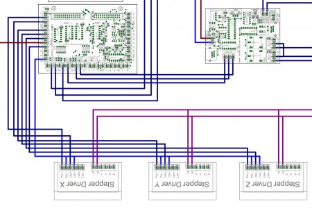
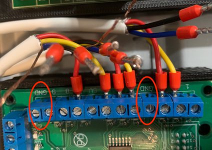
1. Looking at a couple of diagrams, it calls for wiring together (DIR -) and (PUL -) from each Driver and then placing in one of the ground (GND) terminals in the C25 board... the board has several GND terminals... why can I just combine each of the (DIR -) and (PUL -) from each of the driver and connect those to one of the GND terminals... three GND terminals that I can use... why wire it all to just one??
Wiring Diagram.jpg

IMG_3209.jpg

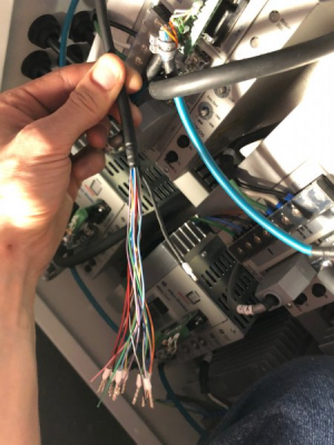
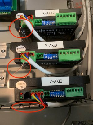
2. What do you do with these? The wire that is not covered in the shielded cable.
IMG_3208.jpg
 
Last edited:
1. Looking at a couple of diagrams, it calls for wiring together (DIR -) and (PUL -) from each Driver and then placing in one of the ground /(GND) terminals in the C25 board... the board has several GND terminals... why can I just combine each of the (DIR -) and (PUL -) from each of the driver and connect those to one of the GND terminals... three GND terminals that I can use... why wire it all to just one??

I'd actually prefer to connect each drive individually back to the C25 GND pins like you suggest. Weird things can happen in circuits with too many daisy chains. These PUL- and DIR- pins are the second connection for differential pair signals. Your ESS produces single ended signals so you'd connect the low side of the differential receiver to GND as a reference. I suspect the drawings looked cleaner with only one return to the GND pins.

A word of caution, in 95% of devices with differential inputs accepting single ended signals, you connect the low side to GND, however there are a few devices that I've run into that require this to be floating - read the manuals.

EDIT: Many consumer and hobby electronics call DC Common GND. Do not confuse this with PE (AC ground from your utility) or EG (Ground that literally comes from a copper bar stuck in the ground nearby). They are not equivalent until you tie your PSU DC Common connection to PE. Do not assume that someone else's panel has the DC power grounded as there are many cases where you would not want it grounded.

2. What do you do with these? The wire that is not covered in the shielded cable.

Those wires are called the "drain" wires in a shielded cable. In grounded DC power (where DC common is connected to Physical/Protective Earth - PE) this wire would be connected to DC common. For ungrounded DC power, this drain wire should go back to the PE grounding bar. The whole point is to absorb EMI which the wires like to pick up like antennas and give it a low impedance path to ground such that it doesn't interfere with electronics function.

These should be connected on only one side, typically near the controller. Doing both could actually make the noise worse.

I usually try to leave these long and wrap them in clear heatshrink and a ferrule. I also seal the edge where the cable jacket has been stripped with a piece of heat shrink. This is to give be room to land the shield and not short against anything else. Picture below shows this except the shield is cut a little short (the little black wire sticking out to the right).

1581632095721.png
 
Last edited:
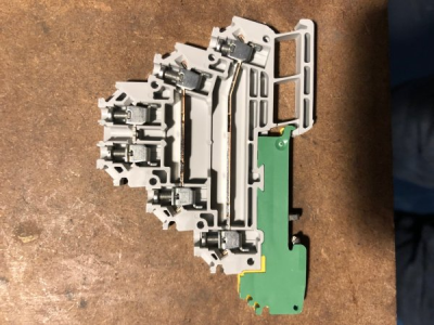
Some terminal blocks, like this 3 tier one from AB that I have been using, have a ground terminal built in specifically for landing shield drain wires from external devices or cables.

1581632335302.png

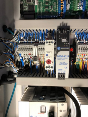
The terminals just to the left of the timing relay (grey) are where this shielded MPG cable landed in my panel.

1581632412099.png

PS: We have the same C25 board:D
 
Okay... let me take them out and start again... I have heat shrink tubing here. Okay, and do the PE grounding bar connection at the board side, got it. I will cut the excess wire at the driver side then heat shrink at both ends.

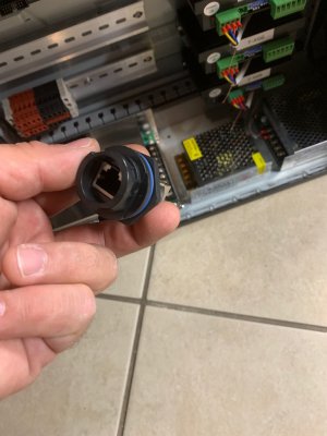
A few things arrived... one of the distribution blocks, 12Volts power supply, pass through RJ45 connector.

IMG_3210.jpg

IMG_3211.jpg

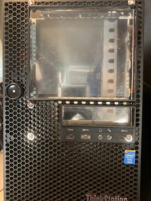
I also cut and installed the cover in front from the left over plexiglass sheet. Need to draw the layout for the connectors to the motors and limit switches.

IMG_3202.jpg
 
Silly post - deleted
 
Last edited:
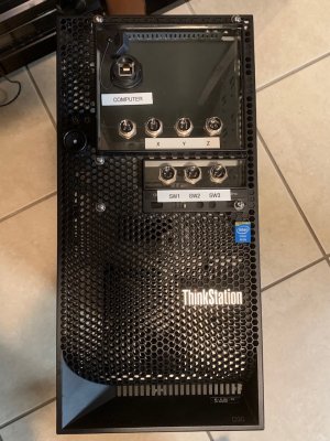
Holes done for connectors and RJ45 passthrough. I forgot to buy the Emergency Stop Switch... :confused:good grief... let me order that.

IMG_3218.jpg
 
Sorry... for those that might to do the same in the future... forgot to include one of the wiring diagrams that I am using. Not my exact configuration, but the only one that I have found that has the C25 with the Ethernet smooth stepper and a speed control board... If I find something better, I will share it. Better yet, maybe after I am done I will search for software to make these diagrams and try to create the diagram for my setup. If I struggled to find one, there has to be others in the same boat...


License is free for 3 years (renewable). It is fully featured but will A) Create a plot stamp that writes "Created by an Autodesk Education Product" (Removable by any PDF editing software), and B) Electronically mark the document as educational content so it cannot be used in a licensed software.

Learning curve is moderate, however it is very valuable to learn if you might ever have a job that requires you to make electrical drawings.

Otherwise, use Sketchup, Visio, Illustrator, PowerPoint, or any other normal drawing software.

EDIT: Self-teaching qualifies as "Student". EDU email address not required.

:encourage: Good to know. I have (well, had) their Fusion 360 software... but seems to have expired. Will check how to enable it again and also download the AutoCAD Electrical.
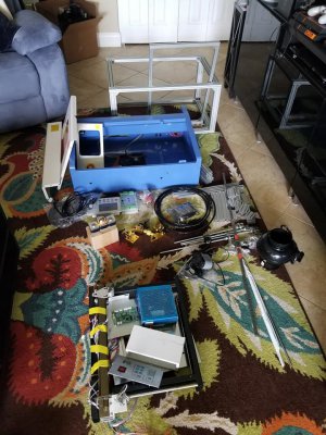
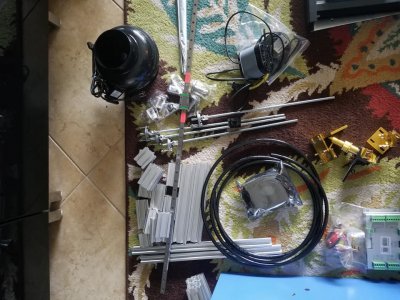
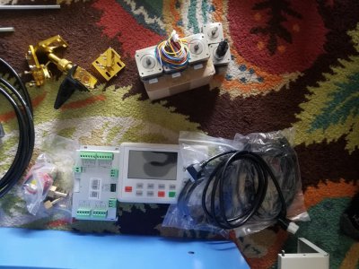
I just got another project, 40 watt laser engraver (that, like many of my projects, requires some assembly :D)... and will need Fusion 360 again to be able to make the designs. I pick it up tomorrow... here are a few photos the seller sent me:


Laser3.jpg
Laser2.jpg
Laser1.jpg
 
Quick update...

Waiting on a safety relay to arrive. Had to get a 24v power supply for that relay.

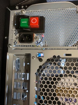
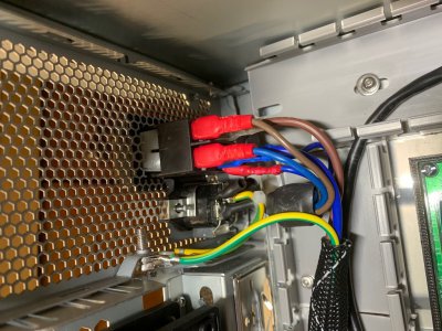
Decided to go back to the receptacle from the computer power supply that I had. I wanted to keep the filter in there and avoid having to build it myself. Also purchased a magnetic switch. All wired up and installed. That sleeve that you see is in addition to the cover that the 12-3 has... I still need to put the heat-shrink cover at each end.

IMG_3248.jpg

IMG_3245.jpg

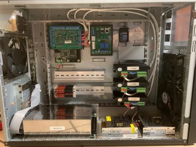
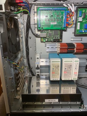
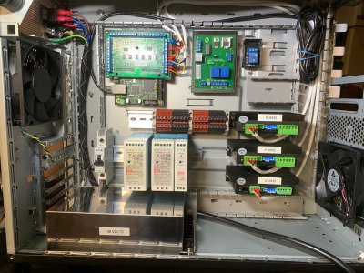
Decided to change the 24v, 12, and 5v DC power supplies.... all those arrived and installed. Had to rearrange the rails as the three PS are larger than I expected. Also installed the 10AMP breaker.

IMG_3254.jpg

Also moved the C6 board further apart from the C25 board.

IMG_3251.jpg

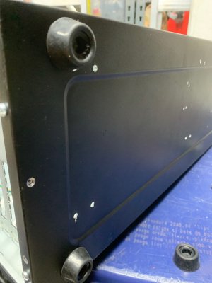
Used 4 pool cue rubber ends as legs for the case.

IMG_3244.jpg

Will now continue to wire the rest...
 
Back
Top