-
Welcome back Guest! Did you know you can mentor other members here at H-M? If not, please check out our Relaunch of Hobby Machinist Mentoring Program!
You are using an out of date browser. It may not display this or other websites correctly.
You should upgrade or use an alternative browser.
You should upgrade or use an alternative browser.
G0704 CNC Conversion (yes, another thread on this :) )
- Thread starter wachuko
- Start date
- Joined
- Aug 6, 2015
- Messages
- 3,886
Done... so easy to get confuse with all the wire colors as you match to the cable... I used the diagram on the first page to convert from 8 wires to 4 wires Bipolar (Series) connection... Checked continuity for each set of coils and wire it up...
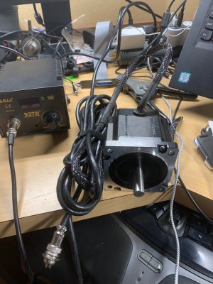
I have it all so that the pins on the connectors are:
Pin1: A+
Pin2: A-
Pin3: B-
Pin4: B+
Easier for me to then remember the wiring order from the connectors to the stepper drivers.

I have it all so that the pins on the connectors are:
Pin1: A+
Pin2: A-
Pin3: B-
Pin4: B+
Easier for me to then remember the wiring order from the connectors to the stepper drivers.
- Joined
- Aug 6, 2015
- Messages
- 3,886
- Joined
- Aug 6, 2015
- Messages
- 3,886
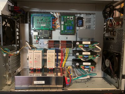
Well... thinking of doing a test run without the safety relay in place...
What could go wrong, right?
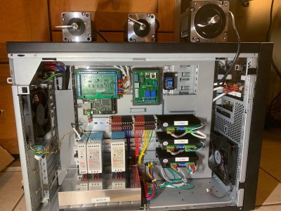
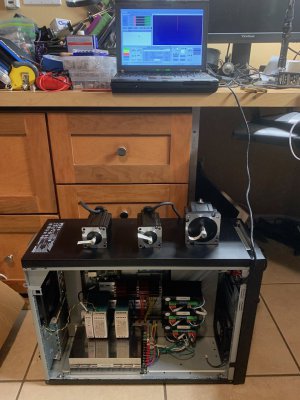
I had the ethernet cable directly from the board to the computer for the initial tests.... but then connected that to the passthrough port to test that as well... All working as expected. I need to get a shorter ethernet cable to put inside the case. The one currently in there is too long...
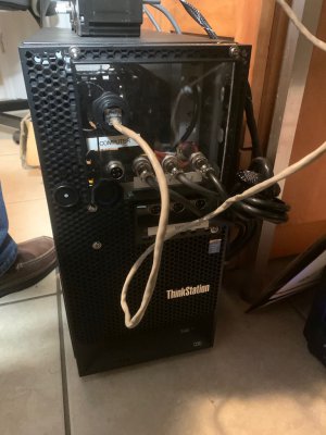
What could go wrong, right?


I had the ethernet cable directly from the board to the computer for the initial tests.... but then connected that to the passthrough port to test that as well... All working as expected. I need to get a shorter ethernet cable to put inside the case. The one currently in there is too long...

Last edited:
- Joined
- Aug 6, 2015
- Messages
- 3,886
Could not resist... had to give it a go....
Only question/concern that I have. Z-axis motor gets warm without using it. Is that normal? Did I wired something wrong? The X and Y 23 stay cool to the touch without activating them... the Z, without activating it, is warm to the touch...
Videos:
Manually controlling the motors
Running a demo program Mach4 had
- Joined
- Aug 6, 2015
- Messages
- 3,886
On the Z-axis motor... I wonder if it has to do with dip switches configuration... but even with Mach4 turned off I can feel the motor... like it is humming... where the other two are completely off (or at least, I can't feel any vibration in them)...
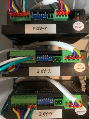
I should be setting all dirvers to the same steps values, correct? X and Y are the same drivers, Z is a different driver...
I see that I now have them set differently (pin settings are the same, but being different drivers, they are set at different steps/rev settings...
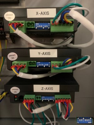
Current with the way the photo above shows:
Z - SW5-On/SW6-On/SW7-On/SW8-Off = 1000 Steps/rev
X - SW5-Off/SW6-Off/SW7-On/SW8-On = 1600 Steps/rev
Y - SW5-Off/SW6-Off/SW7-On/SW8-On = 1600 Steps/rev
So I know that can be changed... but what should I change it to? All to 1000 Steps/rev? Or?
Also, current setting??? Currently, base on the photo shared:
Z - SW1-Off/SW2-On/SW3-On = Peak Current 6.1A / RMS 4.3A also SW4-Off meaning that the standstill curren is set to be half of the selected dynamic current... whatever that means.
X - SW1-Off/SW2-On/SW3-On = Peak Current 5.6A / RMS 4.0A also SW4-Off meaning that the standstill curren is set to be half of the selected dynamic current... whatever that means.
Y - SW1-Off/SW2-On/SW3-On = Peak Current 5.6A / RMS 4.0A also SW4-Off meaning that the standstill curren is set to be half of the selected dynamic current... whatever that means.
Guidance here would be extremely appreciated...
- Joined
- Aug 6, 2015
- Messages
- 3,886
- Joined
- Aug 6, 2015
- Messages
- 3,886
On the vibration that I feel when the motor is idle... found and article.
 www.motioncontroltips.com
"When stepper motors operate, they operate by drawing current continuously. This method of operation ensures more accurate positioning and more consistent torque. However, this also means an increase of energy they use and the amount of heat they produce. This holds true even when the stepper motor is idling."
So I am guessing that since it is always receiving current that explains the slight vibration at idle and the warm temperature.
My stepper driver has Automatic idle-current reduction set to off... so at idle it current should be reduced by 60%... I just do not get why the 23 motors do not display any vibration at idle and the 34 does... I am tempted on ordering a 4-wire 34 motor just to compare... I am trying to validate if this is related to my install/configuration or if it is normal
FAQ: What is stepper drive idle-current reduction and why does it help?
When stepper motors operate, they operate by drawing current continuously. This method of operation ensures more accurate positioning and more consistent
"When stepper motors operate, they operate by drawing current continuously. This method of operation ensures more accurate positioning and more consistent torque. However, this also means an increase of energy they use and the amount of heat they produce. This holds true even when the stepper motor is idling."
So I am guessing that since it is always receiving current that explains the slight vibration at idle and the warm temperature.
My stepper driver has Automatic idle-current reduction set to off... so at idle it current should be reduced by 60%... I just do not get why the 23 motors do not display any vibration at idle and the 34 does... I am tempted on ordering a 4-wire 34 motor just to compare... I am trying to validate if this is related to my install/configuration or if it is normal


