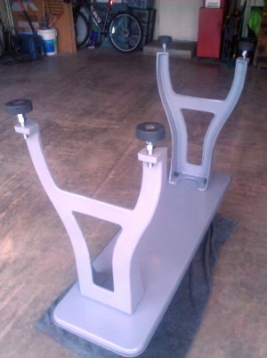
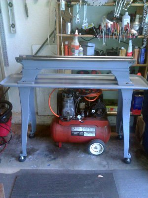
Greg's Logan 820 Restoration

Henry, thanks for the tip, I'll check it out.
I had assumed SHCSs would be too tall, but according to Machinery's Handbook, they should fit. They have the same maximum head diameter (0.313") and have a 0.015" lower max. head height than the fillister heads. ]
Fortunately, the threads in my rack are all still okay.

Greg

I wound up using some 10x32 socket head cap screws to replace the filister heads when I re-attached the rack on my clausing. The fit in the counterbore is snug, but not too tight. I actually neede to helicoil the rack, since only 1 of the four tapped holes had any sort of recognizable threads left :)
 
Great write up. I really appreciate your attention to detail as well as the photo log. I have a Logan 1957 that is begging for a little TLC. Totally understand the constraints of time/space/and cash... God bless.
Jon In Tucson
 
Re: Greg's Logan 820 Restoration - Follow up on the Fillister and Socket Head Cap Screws

So I got some 10x32 SHCS. Turns out their heads are too tall (by 0.085") for the counterbores in the lathe bed, so they don't fit flush. Were they out-of-spec? No, the heads are good (0.189" tall). The problem is with the so-called Fillister head screws that were in my lathe. Proper fillister heads have a curved top -- I don't know what the original Logan-provided screws were, but the heads on mine had been filed or ground down so the heads would fit flush with the ways. This leaves only .025 of screwdriver slot depth, no wonder they got mangled in my struggles to remove them. (Should be at least .064".)

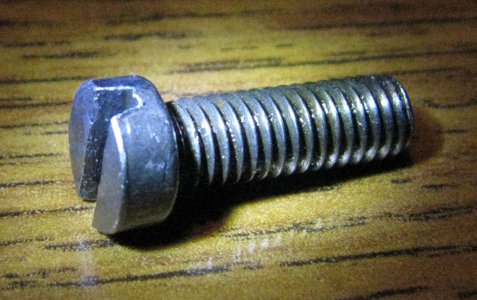
Fellow Logan owners: do the rack-mounting screws fit flush in your lathe's bed? Are they real, standard FHCSs or have they been modified similiar to mine. Here are my "FHCS" and a standard SHCS posing against the Handbook's specs for FHCS.
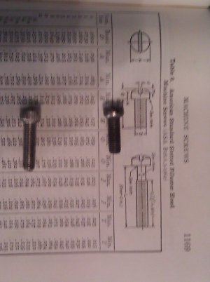
FHCS and SHCS.jpg

Maybe I will just deepen the slots and reinstall the FHCS, at least until I get the lathe back together. Then I can either make new pseudo-fillisters or trim the underside of the SHCS heads so they can go in flush, if needed. Yeah, one screw is hidden under the headstock. I don't plan to remove the headstock again just to change it!

Progress report on the bed, tray and legs restoration
The legs have been tapped for the hockey puck feet, the old paint removed, and primer coats applied. Likewise for the bed feet. Paint also removed from the bed and the chip tray. For the tray, I used an aluminum oxide disk on an angle grinder and it now looks so nice and bright that I'm tempted to leave it bare metal. But I will paint it; and I'm sure it will quickly return to a dirty, stained, and chipped-paint state.

I hope to finish the priming this weekend and do the finishing coats this week. According to my logbook, tomorrow (20 July) will be the one-year mark on this restoration.


from 05July14
Henry, thanks for the tip, I'll check it out.
I had assumed SHCSs would be too tall, but according to Machinery's Handbook, they should fit. They have the same maximum head diameter (0.313") and have a 0.015" lower max. head height than the fillister heads. ]
Fortunately, the threads in my rack are all still okay.

Greg

from 05July14 Originally Posted by hvontres
I wound up using some 10x32 socket head cap screws to replace the filister heads when I re-attached the rack on my clausing. The fit in the counterbore is snug, but not too tight. I actually neede to helicoil the rack, since only 1 of the four tapped holes had any sort of recognizable threads left :)

from 04July14 Originally Posted by gjmontll
...
Removing the rack from the bed was difficult. The six fillister head screws (#10-32 x 9/16") wouldn't budge. Repeated squirts of PB Blaster from above and below did the job in a few hours. I was just about to drill out the final screw but it finally surrendered. Several screw heads suffered wounds during this struggle. I tried to find replacements locally, no luck yet. I may have to make my own after the lathe is running again.
...
Greg


FHCS and SHCS.jpg
 
Last edited by a moderator:
Hey Greg;

I have no way of knowing but no reason to suspect that my rack screws are anything but original. They are flat head slotted screws and the head is about .123 thick. They are just a tick below the bed surface. I cleaned them up a bit because they were naturally a little bunged up. I flatted the heads back down and squared up the slots and reused them. I can add a closeup pic if you like.
 
Redlineman

Thanks for the info, my screws measured similar to your, so I will assume they are also original. I too will clean them up and that should be good for another 70 years.

Greg

Hey Greg;

I have no way of knowing but no reason to suspect that my rack screws are anything but original. They are flat head slotted screws and the head is about .123 thick. They are just a tick below the bed surface. I cleaned them up a bit because they were naturally a little bunged up. I flatted the heads back down and squared up the slots and reused them. I can add a closeup pic if you like.
 
Re: Greg's Logan 820 Restoration - Almost ready for reassembly

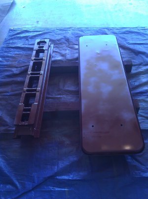
Yesterday I primer painted the last two parts, the bed and the chip tray, and got one side top coated.
bed and tray primed.jpg
This morning I finished the painting (using Rustoleum's Dark Machine Gray.) I will let it set up over the weekend and next week round up the pieces and sub-assemblies and put it all back together.

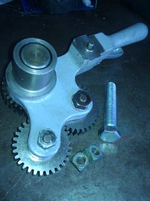
A few weeks ago, I mentioned how the Reverse Gear Lever assembly was supposed to have two 5/16-18 heavy hex nuts" (fatter and taller than normal hex nuts), but one had been replaced by a pair of cheap/incorrect, square nuts. I couldn't find any heavy hex nuts locally. So I made one from a 1/2"hex head bolt.
Heavy hex nut.jpg
The photo shows the assembly with the old and new heavy hex nuts in place, the incorrect square nuts below, and a bolt such as was used to make the nut. I used a 1/2" All-Thread coupler as an indexing fixture to hold the bolt while I milled the head down from 3/4" to ~9/16" across the flats. If you are looking for high precision doing this, note that my coupler's hole was about 0.010"off center. This caused some error on my first cuts, until I realized that I needed to readjust the mill's Z-axis on a face-by-face basis. Interestingly, the original heavy nut was oversize, according to Machinery's Handbook: 8-thou too tall and 40-thou too wide. You can sort of see that in the picture.

Greg

bed and tray primed.jpg Heavy hex nut.jpg
 
Details & Minutia;

I tried to make all of the the fasteners that show original on mine. I'd pick and choose to find those good originals for exposed use, and used generic modern stuff for that which was buried and out of sight. Many would scratch their heads and chuckle at the level of detail shown here, but since it is about The Journey for many of us, I applaud it!!

To that end, here is a pic of the rack screws that G was interested in. This one is representative of what mine look like AFTER truing them up a bit. Not perfect by any stretch, but correct and still useful nonetheless, and they look just fine installed.

LoganCarriageRackScrews.jpg
 
Re: Greg's Logan 820 Restoration - Reassembly First Steps

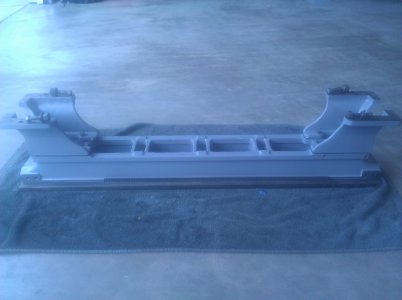
Painting is now completed. Thanks for the picture, Redlineman, I've cleaned up my rack mounting bolts in a similar manner. Now to put everything back together...
First, fasten the rack to the bed, and attach the bed feet.
reassy 1 bed.jpg

Then, put the chip tray in place and bolt the legs on. Doing this with the bed upside down and without the headstock was so much easier than when I bought the lathe 16 months ago. And the hockey puck levelling feet were screwed into the legs. For details on these puck feet, see my entries in this thread from back on 15 and 17 December 2013.
reassy 2 bed trat legs upsidedown.jpg

Flip it over, and I'm done for today.
reassy 3 bed,tray,legs,feet.jpg
Tomorrow, I'll first put the headstock back on, do some levelling, and wrestle the drive unit into position and get it connected, I am using the leather belt with the loops and pin.

Greg

reassy 1 bed.jpg reassy 2 bed trat legs upsidedown.jpg reassy 3 bed,tray,legs,feet.jpg
 
Ha!

I built mine from the ground up, instead of down to it. Whatever gets it done well is the best way! The drive unit is a trick. It is an awfully unwieldy beast when completely assembled. Ideally - while working alone, as I did - you would build it in pieces, I think. However, to do that you need space around it to work, and then be able to move it into place afterwards. If that place is out on an open machine floor, the task is simple. If it is against a garage or basement wall, like most of us, that aint easy! Given the inherent lack of overall mass, the peg leg is a brilliantly simple means of attaching the drive while minimizing its negative impacts on turning material, but it sure makes it hard to maneuver!

Looks great, by the way!
 
Back
Top