Greg's Logan 820 Restoration

What a great looking restoration, I have enjoyed following along and watching it all come together, very nice. I grew up as a kid in San Diego, great place for a kid to grow up. I lived in Clairemont mesa, moved to Michigan when I was 16 in 1976, been here ever since.
 
Re: Greg's Logan 820 Restoration - Spindle Alignment Attempts Continuing (Rollie's Dad's Method)

On and off for two months, I've been trying to measure and improve the headstock/spindle alignment. I've tried a variety of methods and continue to have problems getting it right.

The best method seems to be "Rollie's Dad's Method" (RDM), but I have been making measurements, inserting and removing shims, and cranking on the leveling legs without real success. With RDM, I've been using a 15" piece of 1/2"drill rod in my 4-jaw chuck, taking horizontal and vertical measurements at two "stations", one 1" from the chuck, the other at 13".

The lathe is 70 years old, the ways are obviously worn, maybe this is the problem, especially since maximum wear is typically close to the chuck. And if I adjust the saddle gibs snug when the carriage is at the chuck, it locks up tight by the time I get halfway over to the right. So maybe the alignment problem I'm seeing is not all due to spindle alignment, but also due to irregularities in the ways, particularly since my one measurement point is in that "max wear region.

Today I tested this hypothesis. Rather than just using the two measurement stations (0" and 13"), this time I took measurements at each inch along the rod, stations 0, 1, 2, ... 13. Ät each station, you measure (dial indicator in the tool post) the max and min readings in the horizontal plane, then find the average of those two readings. Repeat the process at each station, but with the dial indicator measuring in the vertical plane.

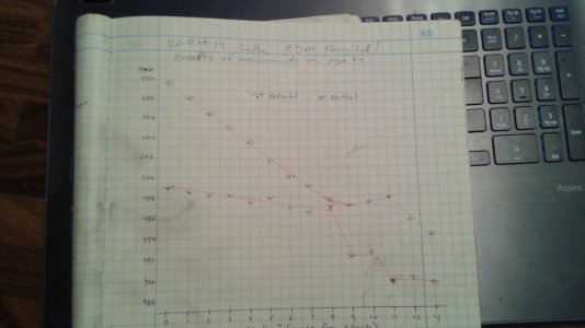
I expected to see irregularities nearest the chuck, but the results are surprising. I'm yet sure what they fully imply and am looking for y'all's ideas. Here is a graph of today's RDM results. I hope you can read this...
rdm 13 station graph 20Oct14.jpg


On the Y-axis is the averaged dial indicator readings, in thousandths. On the X-axis are the measurement stations (inches from the chuck). There are two curves plotted, the upper one is the horizontal axis measurements, the lower one is the vertical axis. If the lathe was perfectly in alignment (and not worn), the lines would be perfectly horizontal.
Instead, you see that for the first 8 stations (8 inches), the results are nicely linear. Based on the slopes, this indicates an headstock misalignment of 0.016"/foot horizontal and 0.002"/ft vertical. Therefore the horizontal axis needs to tilt forward, toward the tool post (right side of the headstock comes toward me. And the vertical axis needs to tilt upward a bit more (shims under right side of headstock.) OTOH, according to my calculation, that .002/ft is just what the expected sag in the rod would be. A larger test rod would prove/disprove this. (One factor for which RDM does not account is any sag in the test rod.)

But then, starting at station 9, both the horizontal and vertical curves go awry, although they seem to return toward the original slope rates. This tells me something is wrong with the ways around the 8"- 11" range. And this break in the linearities perhaps explains why my initial RDM efforts weren't working right, since I was measuring beyond the linear region.

I would think that the cutting forces would cause wear on the top of the front way (inside of the V-way) and the bottom of the rear way. Is this true? I will investigate tomorrow.

I am tempted to get another, longer piece of drill rod, maybe 5/8"or even 3/4", to enable measuring further down the ways (and reduce/eliminate the sagging rod factor)

Greg

rollies dads horiz.jpg rdm 13 station graph 20Oct14.jpg
 
Re: Greg's Logan 820 Restoration - Spindle Alignment Attempts Continuing (Rollie's Dad's Method)

Go Big, Greg;

I would go for 1" rod even. Or, even the largest that will fit through the spindle. I would think that the amount of deflection on a 1/2 rod not turned between centers would be significant. I assume you are not turning between centers, seeing no quill in your tailstock...

Learn all you can and become an expert at this, 'cause I can see you will be coaching me through this... soon, I hope. The seat of my pants works for a lot of things, but not intricate process, and NOTHING I have works good at math!
 
Re: Greg's Logan 820 Restoration - Rollie's Dad's Method for Spindle Alignment, enhanced version

Redlineman and the gang,

The Logan 820 has a spindle bore of 0.781, so I got a new piece of 3/4" drillr od and cut off a 2 foot piece for a bigger test rod. Bigger is better since it reduces inherent sag in the rod itself. According to my calculations, 13"of 1/2 rod will sag 0.0022, but 3/4 rod will only sag 0.001. But my new 24" rod may sag 0.011 at the end. And the heavy rod may sag more inside my elderly 8" 4-jaw chuck. In retrospect, I should have super torqued the jaws before today's run!

Here are the old 1/2 rod and the new 3/4 one, ready to go.
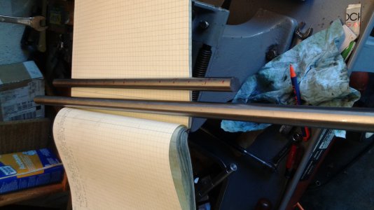
RDM test rods, old and new.jpg
But today's work primarily focused on the horizontal alignment. Based on yesterday's graph, which showed a horizontal error of 0.0177"/foot, I added an 0.008 shim under the right rear corner of the headstock's, on the front side of the vee-way, so as to skew the spindle axis forward.

I marked the rod at every inch, starting near the chuck (station 0) and running out to station 20. Remember yesterday's erratic readings around station 9, now I hope to get a better idea of what's going on. The rear side of the front carriage way did show a series of little marks in that region, you could barely feel them with a needle, but they are "microdents", maybe caused by chattering? Anyhow, I wiped down the ways and tighten all the gibs before today's measurements.

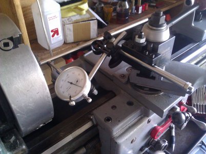
First the horizontal, now that the shim has been added. Here is how the horizontal measurements are done:
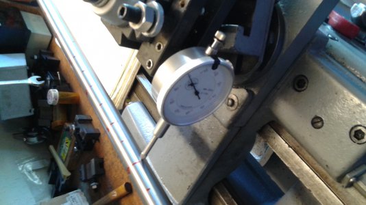
RDM horiz measurements.jpg
Starting at station 0, I crank the carriage in until I getting a nice round reading on the dial indicator such as 0.300, then turn the spindle until I find and record the high and low readings at that station. Today I made a spreadsheet to find the averages and plot them, (note: from here on, I will show numbers like 0.3015 as just "301.5")
Station Max Min Average
0 301.5 298.5 300
1
2
...
And so on: crank the carriage down to the next station, find and record the max and min. Every few inches, I make sure the dial indicator is still on the centerline of the rod. Because of the sag factor, I need to readjust the tool holder height a few times. Be careful not to bump the cross feed or compound cranks!

Then the vertical measurements: I change my tool holders to one with a vertically mounted dial indicator and repeat the station by station measurements of the max and min deflections in order to find the average deflection at each station.
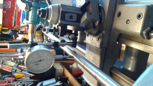
RDM vert measurements.jpg

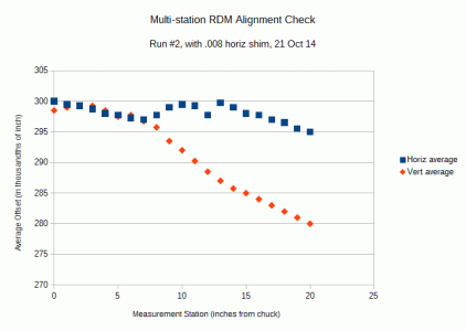
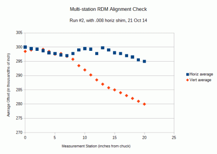
Here are today's results:
RDM 21 station measurements graph 21 Oct.gif
Analysis: The .008 shim has significantly improved the horizontal alignment, going from .0177"/foot of misalignment down to 0.0055"/ft. Therefore, I will add another .004 of shim and that should about zero it out. Note, these slopes are figured in the interval of stations 0 - 7, the nice linear portion. But despite the dips, the full 20"range is not too bad, it works out to 0.003"/ft of error (on average, ignoring the anomalies). I think I could live with that.

But the vertical error is much worse today Is it due to the fatter/longer bar not being clamped tight enough in the chuck?

Redlineman: Do you see what's going on here? Because I am not actually cutting the rod, having a long, thin piece sticking out of the chuck is not a real problem, especially in the horizontal plane. It is just the few grams of pressure from the dial indicator. The nice thing about RDM is that you don't need a perfectly straight rod, nor a perfect, zero-runout chuck. Because the readings are averaged, that accounts for these factors. But it doesn't account for sag, as mentioned earlier, and it doesn't account for variations in the diameter of the rod from station to station. Drill rod should be good, but I will mike it tomorrow, any variations can be compensated for in the spreadsheet if needed.

Tomorrow I have to teach a math class, but may get back into the shop and continue this epic.

Greg

RDM test rods, old and new.jpg RDM horiz measurements.jpg RDM vert measurements.jpg RDM 21 station measurements graph 21 Oct.gif
 
Re: Greg's Logan 820 Restoration - Rollie's Dad's Method for Spindle Alignment, enhanced version

Yes, Master;

Dumb me. This is a static test. Duh. It will be interesting to see how it holds when the rubber meets the road? Drill rod is usually ground to... .0005 or so? Max/min average to account for runout, yes? Maybe I should actually read the RDM to see what it says? I'm not a very good book learner, and tend to reflexively shy away from even trying...

But... I just picked up the sweetest B&S jeweled .0001 reading indicator you ever saw, and for a song. Shipping was more than the purchase price. I still can't believe it! Oh... sorry...
 
Re: Greg's Logan 820 Restoration - Rollie's Dad's Method for Spindle Alignment, enhanced version

Last week I showed the results after shimming the headstock for some horizontal adjustment. I was thinking the vertical error might in part be from an inadequately-tightened chuck, and from inherent sag in the 23 inches of 3/4" drill rod.

So, I really tighened the chuck and checked that the drill rod did have a uniform diameter. It was uniform, within the accuracy/precision of my micrometer and calipers. In the horizontal axis, I had been close to alignment, so rather than adding more shim, I raised the right front leg by using my homemade adjustable leveling feet.

Remember the anomaly starting at around 8" inches from the chuck? Here, again is last week's plot of the horizontal and vertical misalignments. As I said, ideally the lines would be straight and flat.
RDM 21 station measurements graph 21 Oct.gif
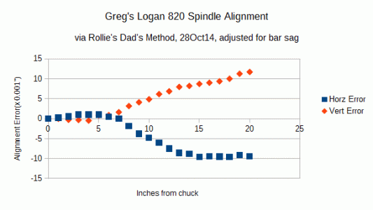
Now, here is the latest plot. Note that I've changed the Y-axis from the averaged dial indicator offset readings, to a zero-based alignment error. Regardless, the lines should still, ideally be flat and straight.
Greg's Logan 820 Spindle Alignment, RDM with sag adjust, 28Oct14.gif

At least for the first 7 inches, this looks great. The question remains: is this an illustration of really badly-worn ways, or maybe a bent bed?

Most of my unsupported turning should/will probably be close to the chuck, or I else I should/will be supporting with the tailstock center or a steady rest. So I think I am happy with this. Checking/fixing the tailstock-to-spindle alignment is the next challenge!

Rather than optimizing the alignment in the first seven inches, I wonder if I should try to zero the error at some other point, for example at the 13 inch point. Visualize the two curves maintaining their shape, but rotating around their origins. Depending on what is causing the nonlinearity, that might give much better overall alignment, but may induce way more error in the first several inches. Anybody got ideas on that?

About the sagging bar issue, I think I've learned how to figure the amount of deflection. (assisted by Machinery's Handbook, Engineering Drawing and Design, Wikipedia, and other sources.) I think the deflection is about 0.0011 at 6", 0.0036"at 12", and 0.0072" at 18". These numbers are for 23"of 3/4" steel.

Checking/fixing the tailstock-to-spindle alignment is the next challenge!

Greg

RDM 21 station measurements graph 21 Oct.gif Greg's Logan 820 Spindle Alignment, RDM with sag adjust, 28Oct14.gif
 
Last edited by a moderator:
Re: Greg's Logan 820 Restoration - Rollie's Dad's Method for Spindle Alignment, enhanced version

Dang ... you guys are making my poor old head hurt!! Don't get me wrong, nice work ... but I guess I have to reread on a day I have not already exhausted my few brain cells at work.
 
Re: Greg's Logan 820 Restoration - Rollie's Dad's Method for Spindle Alignment, enhanced version

I Hear Ya, Ed;

He's dun spun my head around a few times too. A real Process Guy! Greg, I believe you are speaking of trying to average your variation between early and mid travel on the bed, to achieve a balanced result between them? At the very least, it would be interesting to see if, and how, you might achieve that, and whether you were actually able to make it better or not? Could be quite illustrative. A scientific method employing one type of change - say, pad jacking - then a return to zero again (if you could get there), then another - as in shimming - to see how each effects the status, offering some idea of which might be a more effective means of getting where you want to go. If I read you correctly, in general, I agree with your thought that an averaged deviation across the bed might prove more useful overall. Only if you planned to do short work would it not make sense, of course.

A side to this is not getting caught up in minutia, which is so dang easy. I was indicating a drill press quill in on the mill yesterday, to shave the base surface of the quill stay bracket flat. I was using that "new" .0001 indicator I spoke of. Man... I got it indicated to about .0004!... until I snugged my X-travel on the mill. Dang!!!... added about another thou of deviation again.

CRAP! :panic:

(Stops... Shakes head...) .0014"... Ummm... That's pretty close, eh? Sure... I nudged it back to 4/10ths again... but just to show I could!! :jester:
 
Re: Greg's Logan 820 Restoration - Rollie's Dad's Method for Spindle Alignment, enhanced version

Guys, thanks for the comments.

I think that before I make any more changes, I want to evaluate the tailstock alignment.
I already know that it is significantly out-of-alignment, and there are more variables in the tailstock alignment; a full assessment will be difficult. I have read about a variety of techniques and will try some of them. Also, I think I will use Rollie's Dad's Method to measure the tailstock axis, similiar to how I did the headstock axis.

About the pad jacking screws on the feet: The horizontal spindle alignment is quite sensitive to the jacking action which twists the bed, but it seems to me that the vertical alignment should not nearly be responsive, particularly if the horizontal alignment is nearly right. But the big limitation of my pad jacks is the limited range of effectiveness. You have to ensure that all four (or five) feet are on the floor; I was making progress in the twisting until the right rear foot came free. Ideally the pads should be anchored to the floor; then you could twist away through a greater range. In my crowded garage, that's not happening. So I shim a bit then try the legs.

Greg


I Hear Ya, Ed;

He's dun spun my head around a few times too. A real Process Guy! Greg, I believe you are speaking of trying to average your variation between early and mid travel on the bed, to achieve a balanced result between them? At the very least, it would be interesting to see if, and how, you might achieve that, and whether you were actually able to make it better or not? Could be quite illustrative. A scientific method employing one type of change - say, pad jacking - then a return to zero again (if you could get there), then another - as in shimming - to see how each effects the status, offering some idea of which might be a more effective means of getting where you want to go. If I read you correctly, in general, I agree with your thought that an averaged deviation across the bed might prove more useful overall. Only if you planned to do short work would it not make sense, of course.

A side to this is not getting caught up in minutia, which is so dang easy. I was indicating a drill press quill in on the mill yesterday, to shave the base surface of the quill stay bracket flat. I was using that "new" .0001 indicator I spoke of. Man... I got it indicated to about .0004!... until I snugged my X-travel on the mill. Dang!!!... added about another thou of deviation again.

CRAP! :panic:

(Stops... Shakes head...) .0014"... Ummm... That's pretty close, eh? Sure... I nudged it back to 4/10ths again... but just to show I could!! :jester:
 
Re: Greg's Logan 820 Restoration - Rollie's Dad's Method for Spindle Alignment, enhanced version

You have to ensure that all four (or five) feet are on the floor; I was making progress in the twisting until the right rear foot came free. Ideally the pads should be anchored to the floor; then you could twist away through a greater range. In my crowded garage, that's not happening. So I shim a bit then try the legs.

This is harder than it sounds. I recently moved my lathe 18", and because my garage floor is so uneven, that meant starting over leveling it again. That 5th "leg" makes it very difficult to get the other 4 even. It exerts a lot of twisting force on the bed unless it is very well aligned. Problem is you can't do one or the other, they have to all be adjusted together. Each affects the others. I went through several tries only to find 1 foot that wasn't touching the floor. At one point I gave up and waited for another day. That helped!

GG
 
Back
Top