Greg's Logan 820 Restoration

Re: Greg's Logan 820 Restoration - Tailstock Alignment, Part 1 of ?

Previously I thought I might adapt Rollie's Dad's Method (RDM) of headstock alignment to the tailstock too. At least for now, not going to do that.

Instead I used the method shown on YouTube by Halligan142 in his South Bend Lathe Tailstock Alignment.
(
https://www.youtube.com/watch?v=MmMmM8B40bs )
His video shows how to make and use a test bar to measure and adjust the tailstock for alignment with the spindle axis in both the horizontal and vertical axes. And the nice feature is that the tailstock doesn't need to be closely aligned to make a good test bar!

Note: Hoping to be unambiguous in my narrative, I'll reference the tailstock in nautical directions: fore and aft, port and starboard; with bow being the quill and the stern the handwheel, port is closest to you and starboard is the "back".

Using 1/2" steel rod, I first made a 12" test bar and used it.

After overhauling the tailstock, of course it was out in the horizontal (y-axis?), this is more or less easily fixed using the port and starboard adjustment screws. The difficulty is an apparent sloppiness in the tailstock's positioning as it tightens down against the bed. I would thing that with the vee-shaped way, even with wear on the ways and tailstock, that I would get repeatable readings. But loosening the tailstock, moving right and back left to re-engage the test rod and retightening everthing (tailstock clamp, quill/center against test rod, and quill lock) sometimes seems to have about 0.002" of variance. Anybody got ideas on this?

The vertical alignment was also out, as a first pass, I inserted 0.0116" shims at both ends (fore and aft) of the tailstock. This is now very close to zero, at least with the tailstock positioned to engage the 12" test bar with the quill extended to about mid-travel (i.e. at the 1" point.)

But I also measured the horiz and vert errors with the quill positioned at its 0" and 2" marks. This should tell me whether the quill travel is parallel to the spindle, or somewhat skewed. The numbers showed the horizontal to be perfect. But the vertical shows a downward slope of about 0.001" offset per inch of quill travel. This implies the bow and stern are unevenly worn. I will work out the geometry and adjust the shimming a bit. This may be irrelevant when turning work, but import on deep drilling. (Which will be important in my upcoming model artillery project!)

After 70 years of use, I know the carriage ways are worn. What about the tailstock's ways? (For those of you not familiar with the Logans, the carriage and tailstock each have their own pair of ways, one flat way and one vee-way.) To check this, I just made a few more test rods, so I can also measure near the chuck, and elsewhere.

My set now consists of 3", 6", 9", 12", and 18" rods, pictured below, notice how the measurement surface is turned down at the left end of each bar. Flip it end for end to measure at the headstock and then at the tailstock end. By the way, for each measurement, I've actually measured the min and max readings as I rotate the rod, then use the average.
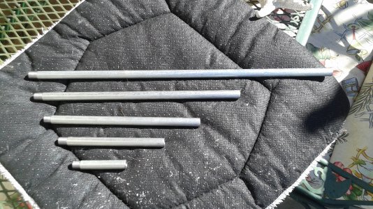
tailstock test bars.jpg

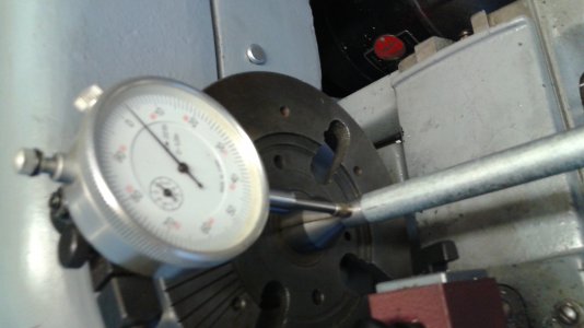
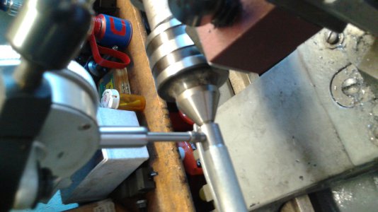
I will go take the measurements and see what's next. And shown below: the setup for taking the vertical and horizontal measurements at the spindle and tailstock ends of the test bar. You'll notice I use a live center in the tailstock, a potential for unnecessary error. But its bearings are tight and the extra extension it provides is needed to get the carriage into measuring position without come up short against the bow of the tailstock.
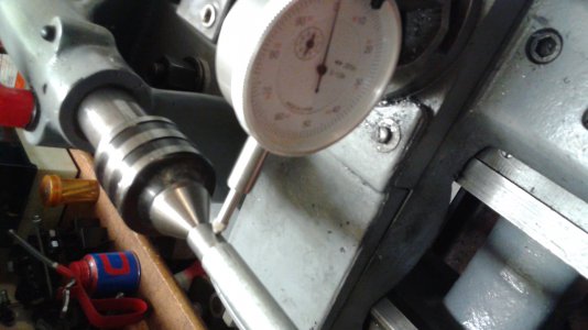
tailstock align horiz at ts.jpgtailstock align vert at chuck.jpgtailstock alignment vert at ts.jpg

Okay, off the the computer and out to the shop.
Greg

tailstock test bars.jpg tailstock align horiz at ts.jpg tailstock align vert at chuck.jpg tailstock alignment vert at ts.jpg
 
Hi Greg,

I have been reading your rebuild with interest. I am rebuilding my Logan 820. I have industrial machine leveling legs under my cast iron legs. However, after reading your leveling issues, I plan on pouring a perfectly flat concrete pad where my lathe will go. The garages in old San Francisco buildings slop a lot to a floor drain. So....

My other problem is the bearings. I have spent a week researching the issue. You can see my other posts on that. If I don't get a thoughtful answer soon, I am going to make a new bearing cover that will reduce the headstock bore by 12MM and use NSK headstock specific bearings and can choose my preload.

A lot of good things in your write up that I am using and will continue to do so.

Thanks for taking the time and the photos.

James.
 
James,
Thank you, I'm glad my project has been useful to you. About the sloping floor - that's not just a old SF thing, for attached garages, the California Building Code specifies a slope toward a drain or the main vehicle doorway. A level base is useful if you are using a machinist's level for the adjustment. So your "perfectly flat concrete pad" can certainly be useful. More importantly, from my recent experience, is that the leveling legs, if possible, should be embedded into the concrete. Then, level or not, when you crank on the legs, you easily twist the bed as desired. And not, as was in my case, just end up with one leg in the air and more twist still needed.

Greg

Hi Greg,

I have been reading your rebuild with interest. I am rebuilding my Logan 820. I have industrial machine leveling legs under my cast iron legs. However, after reading your leveling issues, I plan on pouring a perfectly flat concrete pad where my lathe will go. The garages in old San Francisco buildings slop a lot to a floor drain. So....

My other problem is the bearings. I have spent a week researching the issue. You can see my other posts on that. If I don't get a thoughtful answer soon, I am going to make a new bearing cover that will reduce the headstock bore by 12MM and use NSK headstock specific bearings and can choose my preload.

A lot of good things in your write up that I am using and will continue to do so.

Thanks for taking the time and the photos.

James.
 
DO also note - regarding legs in the air - that these things will settle over time, as hard as it is to wrap your head around a lathe bed twisting. I have been leveling mine for the last 6 months, and it is still a work in progress!

Good to hear from you again, Greg. How is the machine work going?
 
James,
Thank you, I'm glad my project has been useful to you. About the sloping floor - that's not just a old SF thing, for attached garages, the California Building Code specifies a slope toward a drain or the main vehicle doorway. A level base is useful if you are using a machinist's level for the adjustment. So your "perfectly flat concrete pad" can certainly be useful. More importantly, from my recent experience, is that the leveling legs, if possible, should be embedded into the concrete. Then, level or not, when you crank on the legs, you easily twist the bed as desired. And not, as was in my case, just end up with one leg in the air and more twist still needed.

Greg
Greg,

I hope you do not mind. I am posting the end of my trail on the spindle bearing topic here as anyone looking to rebuilding an 820 will run across it. If someone wants to read the full topic do a search on Practical Machinist or the Logan Group on Yahoo for "Logan 820 bearing".

James.
********

Hi all,

On the bearing issue. I called and talked with Scott Logan directly. The conversation was somewhat a curt one. He was not interested in talking about the issues of bearing preload tightness vs. bearing preload wear life. Nor was he interested in the Bearing Engineering House(s) engineer comments on the subject.

He just reiterated that his bearings are to the original specification, what ever those are and for whatever original reasoning, like product vs. hobby, may have been made 70 years ago.

Even though it is evident that he has the bearings made to order, he is not interested in offering anything other than the "original preload".

I think what I am going to do is to order his bearing for now. I will measure the preload and note what it is while getting the lathe back together.

Later, I will make a new bearing retaining plate that will double as a bearing housing for the NSK spindle bearings as I talked about in my other posts. I will get a set of NSK spindle bearing with one preload tighter, in their 4 step graduation, and see what the difference ends up being.

This may take until the fall as I have other projects to deal with. But, once I do the comparison, I will try to swing back and post the results.

As an aside, I have had dealing with business in Asia and Europe. I have to say that it seems that in the USA, as a general rule, business people in many sectors seem to not be interested in actually talking with a customer. My Asian and European contacts seem much more interested in being helpful than folks in business in the USA these days not withstanding if you are ordering one or one-thousand items.

It was not that way when I was young, too bad it is all to common these days.

Best, James.
*********************
 
The conversation was somewhat a curt one. He was not interested in talking about the issues of bearing preload tightness vs. bearing preload wear life. Nor was he interested in the Bearing Engineering House(s) engineer comments on the subject.

James, I was so glad to read your comments today about talking with S. Logan. There was a thread about 6-8 months ago (think it was "dealing with Logan Actuator"), where I was the only one (possibly one other) who was unhappy after trying to speak to Mr. Logan. I have still gone out of my way so as to not buy anything from him, because of his unwillingness to help me. Thanks for the validation, and Greg, sorry for going off topic. JR49
 
James, I was so glad to read your comments today about talking with S. Logan. There was a thread about 6-8 months ago (think it was "dealing with Logan Actuator"), where I was the only one (possibly one other) who was unhappy after trying to speak to Mr. Logan. I have still gone out of my way so as to not buy anything from him, because of his unwillingness to help me. Thanks for the validation, and Greg, sorry for going off topic. JR49

JR, He was not nasty. He just was not interested in the possibility of expanding his product offering. All of us that run a business understand that. What was annoying was the tone. He could have spent a few minutes talking about the information I have received from the bearing maker engineers and others. I made it clear that I was a novice and gave him an opportunity to educate me. Even if he has not interested in making a part available, he could have taken 10 minutes to go into a discussion of the merits.

Perhaps the lathe parts supply business is just a small fraction of what Logan Actuator does these days and he finds such inquires as to much of a distraction. If he had just said so, it would have been more to my personal way of doing business communications than not acknowledging, in a meaningful way, what I was trying to discuss.

I will continue to buy things that I need for the lathe from Logan Actuator, but, I also will not go out of my way to do so either. Support is a two way street in the hobby world.

James.

************
I hope this response is not considered offensive by this forums rules. If so then the moderator can delete it.
***********
 
Last edited by a moderator:
Wow, some of the restorations on this site just blow me away. I'm not sure I have the patience myself, but it is nice to see what can be done.
 
Re: Greg's Logan 820 Restoration - Reassembly: progress and a problem

View attachment 81685

A week ago, the first part of the reassembly went smoothly. Installed the QCGB and lead screw, apron and saddle, and tool post. Roughly positioned the headstock in preparation for alignment. Then I wrestled the drive unit into place and pinned it to the headstock. The belt is not yet on, nor are the top and side covers. Nor is the gear train.

Similar to the alignment tests I did before the reassembly, I began using the "Rollie's Dad's Method" (RDM) using a guide rod (~3/8"diam) out of a printer, as is commonly suggested. Note: back in December, before the teardown, RDM told me the spindle axis was skewed 0.0037/foot rearward, and 0.0054/foot downward.

First I leveled the ways in both X and Y, then took the RDM measurements. There's significant horizontal play available in the headstock's position; a bit of trial and error postioning/tightening and I got to about 10 thous (0.0100/ft) before switching to check the vertical axis. The vertical seems to be 19.0 low (From here on, I'll omit the thousandths/ft in my numbers.) I spent the rest of the afternoon messing with shims, getting closer, but not close enough.

A bit more reading on RDM. It appears to be controversial, and is not the professional way. Once I get the machine powered up, I will cut a test rod, but for now, it seems adequate. Except that it does not account for any possible sag in the test rod.

So, yesterday, I switched from that printer shaft to a piece of 5/8" drill rod. It still showed that the axis was low. I added a bit more shim and saw -0.6 (low). Rechecking the horizontal: initially -2 (rear skew). I couldn't get this out by skewing the headstock any further. But it was very responsive to the adjustable levelling legs I had added. Raise the front right leg about half a turn put enough twist in the bed to end up with -0.3 horizontal and -0.2 vertical. Enough alignment for now, I plan to recheck once it's running. (And as you'll read below, I am going to have to move the headstock!)

Back to the reassembly, I reinstalled the Reverse Gear Assembly and the Change Gear Assembly, setting the gear lash with ordinary paper strips. But now I have a problem. I can't get the "Stop Bracket" (LA-510) to properly position. If I position it to allow the proper gear mesh, then I can't close the side cover. Here is a picture of my problem, and pictures from before the disassembly. I've had this bracket on and off before and I don't see what I'm doing wrong. Any of you Logan guys have the answer?
View attachment 81691
Here are the reference shots. In this case, they haven't helped! Now, the slot in the bracket doesn't go down far enough to let the bracket go nearly vertical to clear the hinge bracket.
View attachment 81692View attachment 81693
And another question for Team Logan: Is the left end of your headstock flush with the end of the bed, or not? Is it offset a bit? Which way and how much? Now that I have it bolted down and reasonably aligned but offset about 1/16" to the right, as a consequence I see my spindle gear doesn't fully engage the width of the drive gear. And belatedly, I look back in my disassembly notes from 25 March and see that before removal, it was offset to the left by 0.108. Maybe this is also the cause of my bracket problem? I'll play with it this afternoon.

Greg

View attachment 81685 View attachment 81691 View attachment 81692 View attachment 81693
Greg, I just finished restoring a model 821 (just like the 820, but 31" center to center). At least that is what I believe is the only difference. I too am having an issue with the getting the side gear cover to close when the gears are meshed to drive the lead screw. Did you resolve this? Looking for an answer....thanks! Really enjoyed your write up and all the photos!!
 
Greg, I just finished restoring a model 821 (just like the 820, but 31" center to center). At least that is what I believe is the only difference. I too am having an issue with the getting the side gear cover to close when the gears are meshed to drive the lead screw. Did you resolve this? Looking for an answer....thanks! Really enjoyed your write up and all the photos!!
It wasn't until quite some time later that I found the problem.
I had set up to cut some threads. As proper procedure calls for, I'd made a very light first pass then checked the resulting thread pitch. It was wrong, therefore I'd assembled the gear train wrong.
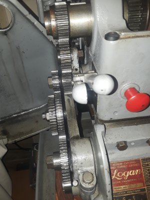
My mistake had been to place the lead screw's gear at the outer position and the spacer inboard. I reversed them. Fixing it also allowed the gear cover to properly close.
I just took this picture to show the difference.
 

Attachments

  • corrected gear train.jpg
    corrected gear train.jpg
    1.3 MB · Views: 15
Back
Top