Re: Greg's Logan 820 Restoration - Tailstock Alignment, Part 1 of ?
Previously I thought I might adapt Rollie's Dad's Method (RDM) of headstock alignment to the tailstock too. At least for now, not going to do that.
Instead I used the method shown on YouTube by Halligan142 in his South Bend Lathe Tailstock Alignment.
( https://www.youtube.com/watch?v=MmMmM8B40bs )
His video shows how to make and use a test bar to measure and adjust the tailstock for alignment with the spindle axis in both the horizontal and vertical axes. And the nice feature is that the tailstock doesn't need to be closely aligned to make a good test bar!
Note: Hoping to be unambiguous in my narrative, I'll reference the tailstock in nautical directions: fore and aft, port and starboard; with bow being the quill and the stern the handwheel, port is closest to you and starboard is the "back".
Using 1/2" steel rod, I first made a 12" test bar and used it.
After overhauling the tailstock, of course it was out in the horizontal (y-axis?), this is more or less easily fixed using the port and starboard adjustment screws. The difficulty is an apparent sloppiness in the tailstock's positioning as it tightens down against the bed. I would thing that with the vee-shaped way, even with wear on the ways and tailstock, that I would get repeatable readings. But loosening the tailstock, moving right and back left to re-engage the test rod and retightening everthing (tailstock clamp, quill/center against test rod, and quill lock) sometimes seems to have about 0.002" of variance. Anybody got ideas on this?
The vertical alignment was also out, as a first pass, I inserted 0.0116" shims at both ends (fore and aft) of the tailstock. This is now very close to zero, at least with the tailstock positioned to engage the 12" test bar with the quill extended to about mid-travel (i.e. at the 1" point.)
But I also measured the horiz and vert errors with the quill positioned at its 0" and 2" marks. This should tell me whether the quill travel is parallel to the spindle, or somewhat skewed. The numbers showed the horizontal to be perfect. But the vertical shows a downward slope of about 0.001" offset per inch of quill travel. This implies the bow and stern are unevenly worn. I will work out the geometry and adjust the shimming a bit. This may be irrelevant when turning work, but import on deep drilling. (Which will be important in my upcoming model artillery project!)
After 70 years of use, I know the carriage ways are worn. What about the tailstock's ways? (For those of you not familiar with the Logans, the carriage and tailstock each have their own pair of ways, one flat way and one vee-way.) To check this, I just made a few more test rods, so I can also measure near the chuck, and elsewhere.
My set now consists of 3", 6", 9", 12", and 18" rods, pictured below, notice how the measurement surface is turned down at the left end of each bar. Flip it end for end to measure at the headstock and then at the tailstock end. By the way, for each measurement, I've actually measured the min and max readings as I rotate the rod, then use the average.

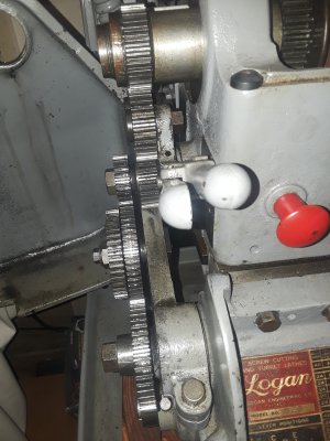
I will go take the measurements and see what's next. And shown below: the setup for taking the vertical and horizontal measurements at the spindle and tailstock ends of the test bar. You'll notice I use a live center in the tailstock, a potential for unnecessary error. But its bearings are tight and the extra extension it provides is needed to get the carriage into measuring position without come up short against the bow of the tailstock.


Okay, off the the computer and out to the shop.
Greg
Previously I thought I might adapt Rollie's Dad's Method (RDM) of headstock alignment to the tailstock too. At least for now, not going to do that.
Instead I used the method shown on YouTube by Halligan142 in his South Bend Lathe Tailstock Alignment.
( https://www.youtube.com/watch?v=MmMmM8B40bs )
His video shows how to make and use a test bar to measure and adjust the tailstock for alignment with the spindle axis in both the horizontal and vertical axes. And the nice feature is that the tailstock doesn't need to be closely aligned to make a good test bar!
Note: Hoping to be unambiguous in my narrative, I'll reference the tailstock in nautical directions: fore and aft, port and starboard; with bow being the quill and the stern the handwheel, port is closest to you and starboard is the "back".
Using 1/2" steel rod, I first made a 12" test bar and used it.
After overhauling the tailstock, of course it was out in the horizontal (y-axis?), this is more or less easily fixed using the port and starboard adjustment screws. The difficulty is an apparent sloppiness in the tailstock's positioning as it tightens down against the bed. I would thing that with the vee-shaped way, even with wear on the ways and tailstock, that I would get repeatable readings. But loosening the tailstock, moving right and back left to re-engage the test rod and retightening everthing (tailstock clamp, quill/center against test rod, and quill lock) sometimes seems to have about 0.002" of variance. Anybody got ideas on this?
The vertical alignment was also out, as a first pass, I inserted 0.0116" shims at both ends (fore and aft) of the tailstock. This is now very close to zero, at least with the tailstock positioned to engage the 12" test bar with the quill extended to about mid-travel (i.e. at the 1" point.)
But I also measured the horiz and vert errors with the quill positioned at its 0" and 2" marks. This should tell me whether the quill travel is parallel to the spindle, or somewhat skewed. The numbers showed the horizontal to be perfect. But the vertical shows a downward slope of about 0.001" offset per inch of quill travel. This implies the bow and stern are unevenly worn. I will work out the geometry and adjust the shimming a bit. This may be irrelevant when turning work, but import on deep drilling. (Which will be important in my upcoming model artillery project!)
After 70 years of use, I know the carriage ways are worn. What about the tailstock's ways? (For those of you not familiar with the Logans, the carriage and tailstock each have their own pair of ways, one flat way and one vee-way.) To check this, I just made a few more test rods, so I can also measure near the chuck, and elsewhere.
My set now consists of 3", 6", 9", 12", and 18" rods, pictured below, notice how the measurement surface is turned down at the left end of each bar. Flip it end for end to measure at the headstock and then at the tailstock end. By the way, for each measurement, I've actually measured the min and max readings as I rotate the rod, then use the average.
I will go take the measurements and see what's next. And shown below: the setup for taking the vertical and horizontal measurements at the spindle and tailstock ends of the test bar. You'll notice I use a live center in the tailstock, a potential for unnecessary error. But its bearings are tight and the extra extension it provides is needed to get the carriage into measuring position without come up short against the bow of the tailstock.
Okay, off the the computer and out to the shop.
Greg