New EMCO Maximat V10 and Mystery Box of Accessories!

@Rich Henderson

First of all, thanks for becoming a Life Member.

I've taken another look at the "what is it" photo and I have a revised opinion regarding the row of cylinders.
IMO, they are all threading die holders (not dies for punches). I now see a setscrew in the OD of a few (for securing the die). I think the through hole is to align the die, better than just using a naked die, coaxial with the workpiece. Sometimes it can be tricky to get such a die to cut coaxial. I think you'll find each through hole is the nominal ID of the intended thread's major diameter. The OD is probably intended to be held in a larger die stock or ???.
 
Last edited:
@Rich Henderson

First of all, thanks for becoming a Life Member.

I've taken another look at the "what is it" photo and I have a revised opinion regarding the row of cylinders.
IMO, they are all threading die holders (not dies for punches). I now see a setscrew in the OD of a few (for securing the die). I think the through hole is to align the die, better than just using a naked die, coaxial with the workpiece. Sometimes it can be tricky to get such a die to cut coaxial. I think you'll find each through hole is the nominal ID of the intended thread's major diameter. The OD is probably intended to be held in a larger die stock or ???.

I think you are right that they are die holders for different sizes with support for the far end. Seems like overkill, but also very Swiss / German / Austrian. :)
 
@Rich Henderson

First of all, thanks for becoming a Life Member.

I've taken another look at the "what is it" photo and I have a revised opinion regarding the row of cylinders.
IMO, they are all threading die holders (not dies for punches). I now see a setscrew in the OD of a few (for securing the die). I think the through hole is to align the die, better than just using a naked die, coaxial with the workpiece. Sometimes it can be tricky to get such a die to cut coaxial. I think you'll find each through hole is the nominal ID of the intended thread's major diameter. The OD is probably intended to be held in a larger die stock or ???.
Yes, they all have set screws so I agree they are all for holding dies. I was thrown off by the different through hole diameters in the back. You would have needed a different tail stock arbor diameter for each one. But now I think you are right. That hole in back takes the unthreaded stock diameter and guarantees the die is concentric with the rod. I supposed I would actually feed the rod from the back through the clearance hole and then up through the dia. Maybe these are made to be chuck mounted.
 
Yes, they all have set screws so I agree they are all for holding dies. I was thrown off by the different through hole diameters in the back. You would have needed a different tail stock arbor diameter for each one. But now I think you are right. That hole in back takes the unthreaded stock diameter and guarantees the die is concentric with the rod. I supposed I would actually feed the rod from the back through the clearance hole and then up through the dia. Maybe these are made to be chuck mounted.

If they work like the die holder I have, the die holder goes in the tailstock, and the piece being threaded goes into the headstock (held by the chuck, collet etc). The die holder usually has a slip fit, so as you turn the stock being threaded the die holder can slide forward pulled further up the rod as it threads.

This is usually done by hand turning the chuck, not under power unless you have an extremely low speed available.

Here is a video showing one in use, you can skip ahead to the 5 min mark to get right to it.

 
The upper right cast item seems to be a mortise attachment for a drill press or mill. Check to see if the large end fits your quill on your milling attachment.

Nice score! I'm sure it nearly broke his heart to part with all of it - it is good that you will put it to great use!
 
Rich - welcome to the forum! I'd have said something earlier, but was "off the air" with a bricked computer for about a week. Here are a couple more idents for your most recent "what is it" photo.

Items near the middle of the 1 1/2'th row - This looks like a woodworker's combination pilot bit and countersink (for a largish wood screw). The "half-tube" goes inside the larger piece (the countersink) and provides clearance for the non-threaded prt of the screw. A drill bit (thread pilot) goes inside the half-tube.

"Ace" 3/8" wrench is for something like a lantern-style tool post.

Just above the bottom row - the bronze part with the diagonal grooves appears to be a precision (bronze?) rack, such as you'd find in the focusing mechanism of a microscope.

Lower right group - one of the items looks like the die for a Greenlee style sheet metal punch. You can confirm this by checking it for hardness.

+1 on your being recognized for major suckage! Among many others, I'll look forward to your next picture full of goodies.
 
@Rich Henderson

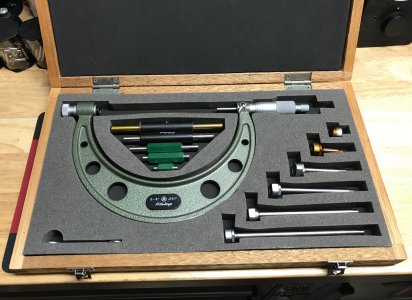
I see that the thin foam layer(s) in your Mitutoyo box is deteriorated. When it looses it's spring-back, it needs to be replaced.
Take the tools out of that box until you replace the thin foam.

I recently posted the following in another thread.

Just in case you're not aware, you need to replace the thin foam layer that the mic is resting on.
I see that the thin foam is deteriorated and, in that condition, it will promote corrosion and damage the metal surfaces in contact.
That is a common problem with vintage Mitutoyo. The form fitting thicker layer seems to hold up well, but the thin layers deteriorate.
I hope the newer Mitutoyo packaging has the chemistry improved, but I don't know.
Originally, there was a thin layer in the top of the box also.
I bought a replacement foam at a craft store. It's a closed cell material, about 3/16 thick. It comes in many colors and easily available on Amazon in 2mm. Just build up layers to get the thickness you need.
Finished that foam replacement in the Mitutoyo micrometer box. Glad you flagged this for me as it appears that the foam was indeed starting to cause some minor corrosion.IMG_4816.jpg
 
Rich - welcome to the forum! I'd have said something earlier, but was "off the air" with a bricked computer for about a week. Here are a couple more idents for your most recent "what is it" photo.

Items near the middle of the 1 1/2'th row - This looks like a woodworker's combination pilot bit and countersink (for a largish wood screw). The "half-tube" goes inside the larger piece (the countersink) and provides clearance for the non-threaded prt of the screw. A drill bit (thread pilot) goes inside the half-tube.

"Ace" 3/8" wrench is for something like a lantern-style tool post.

Just above the bottom row - the bronze part with the diagonal grooves appears to be a precision (bronze?) rack, such as you'd find in the focusing mechanism of a microscope.

Lower right group - one of the items looks like the die for a Greenlee style sheet metal punch. You can confirm this by checking it for hardness.

+1 on your being recognized for major suckage! Among many others, I'll look forward to your next picture full of goodies.
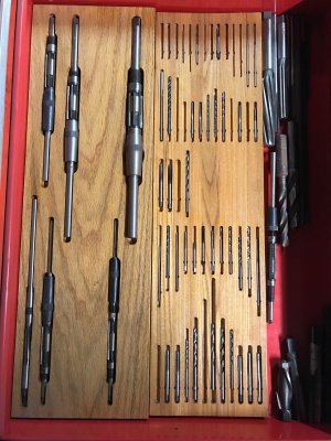
Thanks for the welcome hman. Glad the gears in your computer are turning again. Here comes the next drawer.IMG_4819.jpg
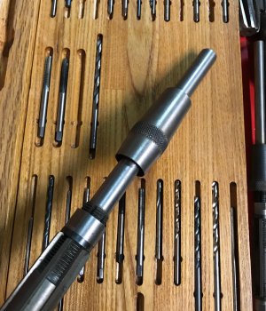
It's an interesting collection of reamers. The ones on the left are adjustable which is neat. Each one has a sliding "hand grip" sort of thing that I'v not seen on a reamer before.IMG_4820.jpg
 
The "hand grip" is a very probably guide sleeve, whose range of diameters should pretty well match the adjustment range of the reamer itself. It's useful if you want to ream a second hole concentric to and inline with an existing hole.
 
Hello all, Its been some time since I have posted but I have been staying plenty busy on my EMCO Maximat V10. I'm in need of some trouble shooting advice. The vertical milling attachment has stopped working and I'm trying to determine if its a problem with the motor or the single phase power.

The failure mode was this: Under any load the milling motor seems to lack torque/power. This got progressively worse until the motor barely had the power to turn the spindle, even with no load. The spindle and gear box spins feely by hand so I don't believe there is any biding or gear damage.

This lathe is running on 110 single phase 60Hz so I believe the vertical milling motor is the same.
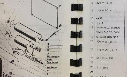
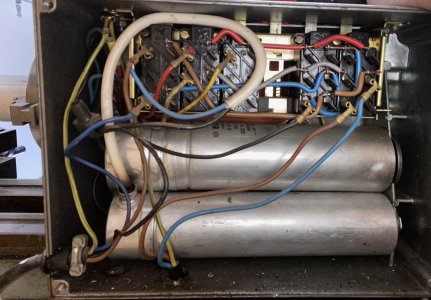
Pictures of the motor, the power distribution box and some shop manuals are shown below. Based on the behavior I'm guessing the capacitors are to blame. Should that be the consensus, where in the world would I find replacements? Is there a modern capacitor solution?

For item 15 and 20 I'm guessing I have the 115V 50uF and the 115v 20uF respectively.
IMG_8050.jpg
Cable coming out of the lower capacitor looks kind of burnt?
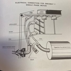
IMG_8046.jpg
I believe this is the wiring for single phase. I think the three phase versions don't have a capacitor.
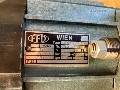
IMG_8047.jpg
Model plate on the vertical motor.
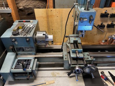
IMG_8044.jpg
And here is the whole lathe.
IMG_8043.jpg
Hope you guys can help.
Many thanks - Rich
 
Back
Top