

Yes that's a power drawbar made out of a HF butterfly impact. Another quarantine project I just completed a week ago. I'm pretty happy how that turned out. There's a ton of threads on making those but I haven't seen anyone use a 3-position momentary valve like that. It was cheap off Amazon and worked out really well.
Regarding the big red E button yeah that's pretty much it. I put the emergency stop there just to provide a means to slap something in a hurry. I also thought it would be useful to have during tool changes or other operations where I might want the mill disabled. Turns out that's completely redundant to center position on the fwd/off/rev switch. I realized that after putting it in. The kill switch lights up indicating power so there's that. lol
I'm happy to provide info on the VFD setup & the parts I used. I have that info somewhere on my computer, just need to dig it up this weekend and I'll post it for you.
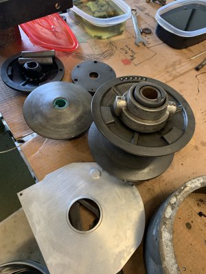


") I see the new detent plates just have a hole milled in the location for the hi engagement. I'm assuming some level of adjustment could be achieved by how the handle is timed on the shaft if I no longer have adjustment where the detent is located?
I see the new detent plates just have a hole milled in the location for the hi engagement. I'm assuming some level of adjustment could be achieved by how the handle is timed on the shaft if I no longer have adjustment where the detent is located?