POTD- PROJECT OF THE DAY: What Did You Make In Your Shop Today?

I was able to begin reassembling the Colchester. I got the gearbox shafts and gears in and aligned, along with the spline shaft and lead screw. I’ve decided I have to do some painting and need help removing the oil level sight glass assembly. I think it’s a press fit from the front but I want to be sure and don’t want to damage it. I want to clean the inside but if it’s too risky, I’ll leave it. Thoughts?
View attachment 472659View attachment 472661
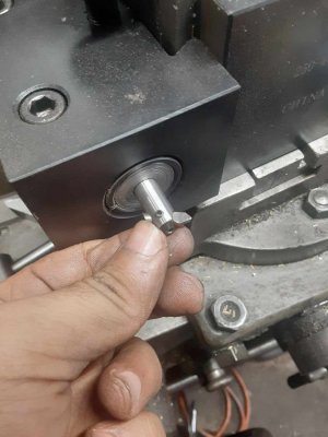
I appears the you may be able to (carefully) pop out the metal cover by using the two holes that allow oil to get into the sight glass cavity: I think the domed disk is holding the probably plastic window against a gasket.

Then you can pressure turn a new disc from thin polycarbonate (I did this to a 12x48 - can’t remember the make - back in the 70’s; wasn’t rebuilding, just cleaning it up and the sight glass was cracked, but clamped with a ring on the outside).
 
Drop the blower if that’s the safest way to do the job.
It it looks like I need to, I will.

The problem is that's a several hour job. It's the blower, front 4pt hitch, the loader frame, and bucket. Some of that is buried behind other stuff put away for winter, that may not start in this weather. At least with the car lift, of anything goes poorly, I'm standing behind the posts.
 
This took allot longer than I intended, but I finally have my counterbores organized, even left some space for new additions. Had to make the second floor standoffs on the lathe. Now I need to do the same for the countersinks!

Happy new year everyone!IMG_0799.jpegIMG_0800.jpegIMG_0801.jpegIMG_0804.jpegIMG_0805.jpegIMG_0806.jpeg
 
A friend needs a replacement finial for his banister. As he lives across the country. I am only working from a couple of photos.

I am proving out my sketch in aluminum before I cut a bronze one.
07953eea6b5711296d2eeba790b513bc.jpg

196ae1f4518bb95dd09f44b4e868ed1b.jpg


Getting the main diameters turned. I will need to make some forming cutters for the various curves. The large curve I will most likely rough it out with 5 or so angle cuts then file to shape. I need to sketch up what angles will work.
c59bdc2f5722dd6512d392f922ecb1ff.jpg


Cutting oil is my blood.
ff742a9cc2d49986a8f9ff7c159d9918.jpg

c30ef735a58c976f5a2a8aaed72992c1.jpg

6b5efd3b8d9402787e12f88a41ce3859.jpg
 
My buddy at Tuckahoe Steam and Gas Association is restoring a Foos gas engine and has had to remake and fabricate many missing parts, one of which was the exhaust flange. He made a pattern and had it cast at a foundry up in Pennsylvania. The exhaust will be 3 inch pipe. My buddy has a pipe threader and can do the external threads but has no way to cut the internal threads in the exhaust flange. So he chucked it up in our big leblond lathe and cut the 3-8 threads. It was tough finding any good information on cutting internal pipe threads on a lathe, but we got it done. Here is a quick video.
 

Attachments

  • 1230231714.mp4
    29.2 MB
Quick and ugly mod to test the idea out. Been annoying me for quite a while everytime I use coolant, it goes absolutely everywhere and the floor becomes a slippery mess, besides losing half the applied coolant.
A lot of it would run out from the side of the saddle and connect under the blue hose.
IMG_8253.JPG

Cut down and bent up some thin aluminium, besides some leaks where they intersect, it helps insanely much with catching applied coolant. Now I just need to make it better looking and extend it to the right. :grin:
IMG_8254.JPG
 
Would probably not recommend following these as instructions. But it seemed to get the job done.

FromThis.jpg ToThis.jpg ThenThis.jpg LastlyThis.jpg

Flipping it without disassembling it was major time saver. It went nice and easy. Just moved a little bit at a time, checking things, while standing well clear.

Not sure that center X really does much. The outer two really stopped any flex in the beams, and stiffened things up really well. Added the center one because the material was there. The openings where there aren't any X ties are where recessed lights may shine through. The bridge can move, but it should be easy enough to position to places where there aren't any shadows on the floor from it.

Anyway...at this point after staring at that pile of steel for WAY too long, I can say the bridge is completed in 2023! With 4 hours to spare even! lol. Next steps will be to fabricate a bunch of little odds and ends that bold on. Bearing supports for the drive shafts, the carriage that carries the chain fall, etc. But the biggest piece is complete.

AndDone.jpg

Happy new year all!
 
Got in my 3/8 easy-bore boring bar so of course i needed a cutter and sleeve adapter to hold her.

This and a steady rest will come in handy to begin the long chain of repairs on my old lathey, hope to be posting a improved tail stock soon enough.
 

Attachments

  • 413970741_1516091985631750_5607747679721381095_n.jpg
    413970741_1516091985631750_5607747679721381095_n.jpg
    195.6 KB · Views: 22
  • 414059298_251180164659394_8165432331001366176_n.jpg
    414059298_251180164659394_8165432331001366176_n.jpg
    234.8 KB · Views: 22
Back
Top