
- Joined
- Dec 18, 2019
- Messages
- 6,446
Use ALM and COM. I'm guessing ALM goes to + and COM to -. I haven't tried this yet, but that's my best guess. I'll be trying this myself within the week.

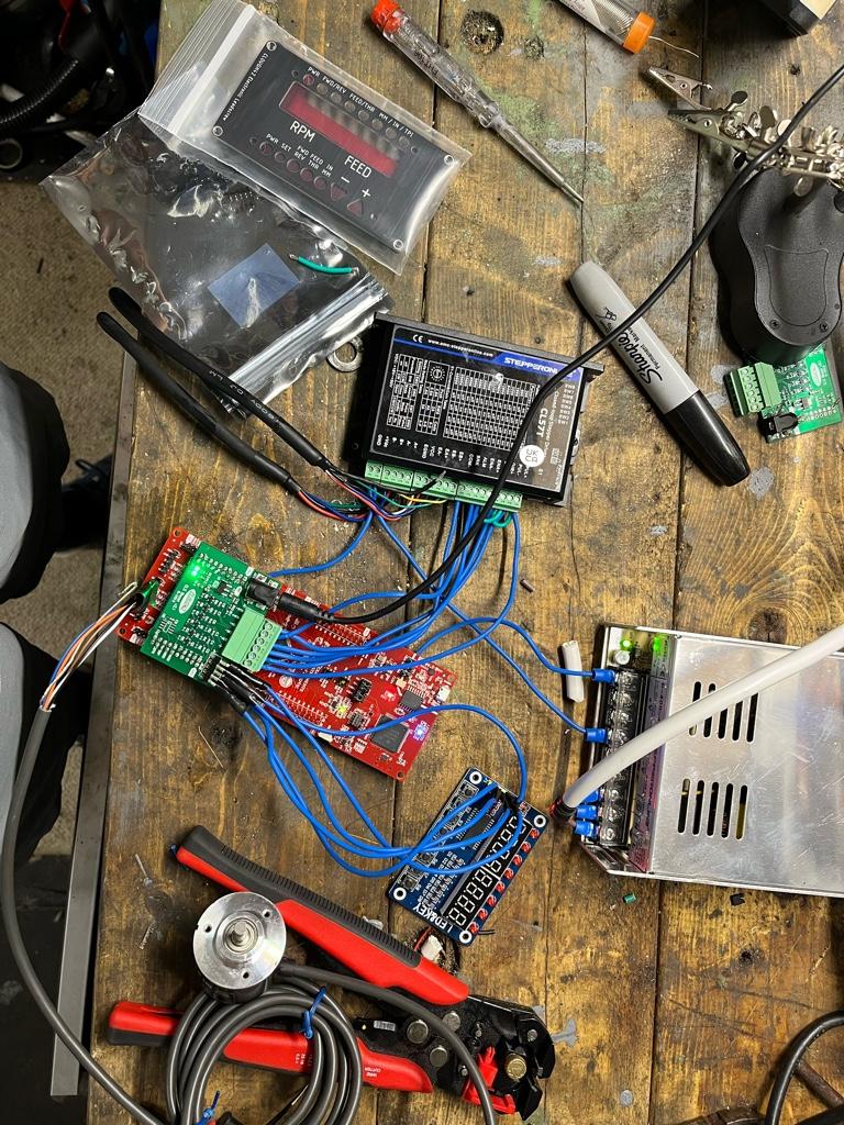
For my G0704, I just got an old computer case. Stripped the inside and used that for installing all parts… Worked well and cost me nothing…
View attachment 424626
View attachment 424627
View attachment 424628

")


I wired in the signals and brought the cabling to my controller, but haven't tried unraveling which is which yet. I will take a look at this within the next day or two. First thing I will try is COM to ground and pull up the ALM signal. Since I have a +3.3V system, I will use a 10K resistor to +3.3V to start. 10K ohms may not be the right value, but the value is high enough that it should be safe to try.@WobblyHand - higher up in the thread you mentioned that you were wiring one of these up yourself and were going to check where ALM and COM connect to. Did you get around to doing that? I connected them as you suggested, just seeing if you've any more info?
I wired in the signals and brought the cabling to my controller, but haven't tried unraveling which is which yet. I will take a look at this within the next day or two. First thing I will try is COM to ground and pull up the ALM signal. Since I have a +3.3V system, I will use a 10K resistor to +3.3V to start. 10K ohms may not be the right value, but the value is high enough that it should be safe to try.
I don't know if this is the case, but try switching the polarity for the ENA signal. By that I mean, if you are using logic 0 for turning on ENA, use logic 1 instead, or vice-versa. I find the documentation on the stepper motor controller is not clear. I had to flip the polarity to get my stepper to work, if I recall correctly. Do not change the wires! This is a software polarity change or there's a variable that controls the sense of the logic. Might work. Might not, but worth checking into.A small amount of progress. I’ve now confirmed that that encoder is wired correctly as I can see RPM readout on the LEDs
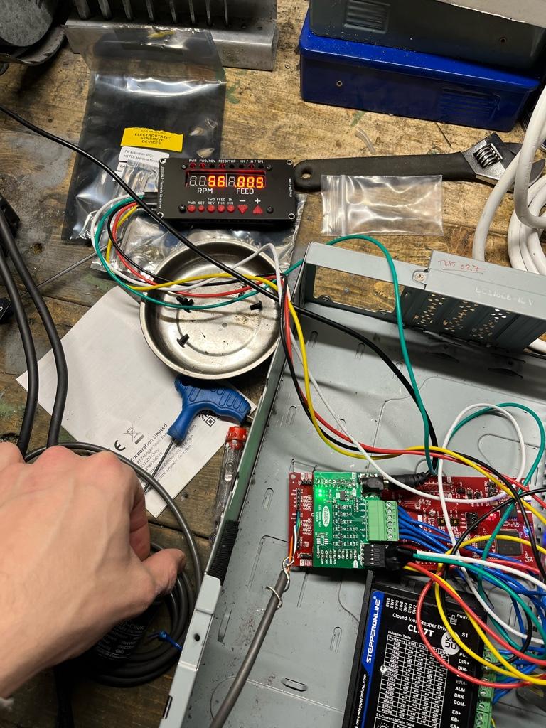
So the issue is the wiring for the stepper motor.
Sent from my iPhone using Tapatalk