- Joined
- Jan 22, 2020
- Messages
- 197
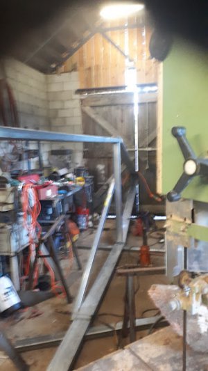
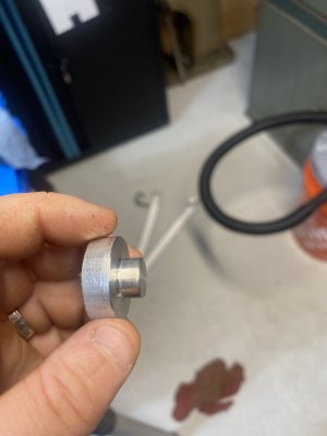
usually I braze iron, but whatever suits you ehThat which cannot be done. Welded and strong. First time welding cast junk. I'm happy.
View attachment 395590View attachment 395591View attachment 395592

usually I braze iron, but whatever suits you ehThat which cannot be done. Welded and strong. First time welding cast junk. I'm happy.
View attachment 395590View attachment 395591View attachment 395592
That mill looks stout (and good price too).no much, got a test sample ex China 8mm thick 5083 plate, bent it sawed it, seems ok
bought an Adcock & Shipley mill and a cold cut off saw that does bevels both 1500,
Alu plate 13000 tonne here 4700 US Tonne ex china, but there is zero stock here plates 8mx2m ie 26 ft x 6 ft 6 inches for a boat build 46 ft long
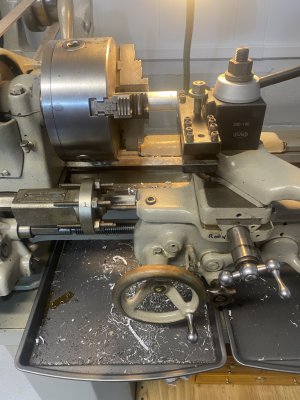
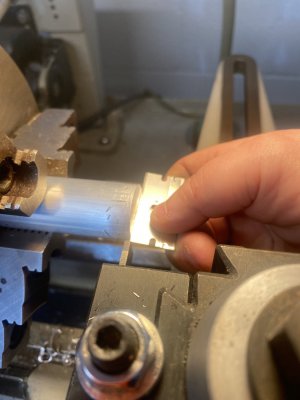
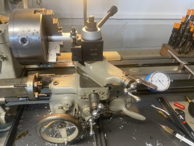


A quick way to resolve the spring is to take a tube solder a tab on it to hold it, and then cut the tube down the length to allow it to fit over the stem and hold the pin out... That's the quick solution. Not the long term solution.Well, yesterday was the day. A day long anticipated. Like 8 years or more. I rounded up the material. Sized it for the project. In a monumental effort to overcome fear and inexperience, I made the cutter. It was a good match to the broken pieces I had carefully preserved. So far so good. The tiny 11 tooth 5/8" diameter broken gear from a reduction gear motor was about to be reborn. Then got out the as yet unused dividing head that came with my new Smithy two years ago. Looked to be pretty well made with good machining quality. It was considerably smaller than the 110 lb behemoth sitting on my shelf, so I could handle it with my recently torn shoulder muscle and mount it on the medium sized Smithy. Assembled the dividing plate system and found Rube Goldbergs best efforts.
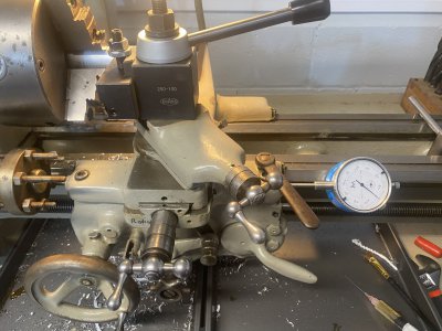
First, the screws that held the dividing plate were protruding above their countersinks causing interference. Fixed that. Sort of. Then the "counting fingers" were secured by a too short 10-32 machine screw jammed part way into a brass 8-32 threaded hole. Fixed that. Then the friction clip that retained the counting fingers wouldn't stay in place. What a rinkydink design! Addressed that issue with at best a temporary fix. Found interference with temp fix and locating pin on the crank. Fixed that. Then worked out the math for 11 divisions on what I assumed was 40:1 because that's more common and there were no markings. So after a test the puzzling results were reviewed and I started from scratch verifying the ratio. 90:1. Solved that problem. After many efforts to successfully operate the crank with a much too heavy locating pin spring, I longed for a way to lock the pin out while cranking so it wouldn't catch the counting fingers and move them inadvertently. There just didn't seem to be any way to make that happen. So I was tired and pretty discouraged, ready to give up.
More coffee.
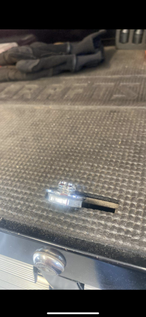
Took the crank apart, disassembled the locating pin with its much too heavy spring and (you guessed it) SPROINNNNNG. Regardless of my best efforts to contain the inevitable. Fortunately the shop was clean enough and the part big enough that I found it in spite of the blue haze. While waiting for an inspiration, I laid out the parts and began to measure them thinking that I would find that useful in designing something in FreeCAD. FreeCAD. That is another formidable obstacle because I trained myself on AutoCAD from its inception somewhere in the 1980s. Long ago, the commercial CADs priced themselves beyond my reach, so I'm trying to learn a whole new modeling work flow philosophy. Partly it's entertainment, barely useful.
That was where I collapsed for the evening, too tired and frustrated to think about translating the now measured parts into virtual reality for idea manipulation. That may be today's task. I do have an idea. Involves making some new parts. But the experience has made me feel like the war was lost for want of a nail.
More coffee.
DanK
Sounds like the way some of my projects go, fix six things before being able to work on the first project.Well, yesterday was the day. A day long anticipated. Like 8 years or more. I rounded up the material. Sized it for the project. In a monumental effort to overcome fear and inexperience, I made the cutter. It was a good match to the broken pieces I had carefully preserved. So far so good. The tiny 11 tooth 5/8" diameter broken gear from a reduction gear motor was about to be reborn. Then got out the as yet unused dividing head that came with my new Smithy two years ago. Looked to be pretty well made with good machining quality. It was considerably smaller than the 110 lb behemoth sitting on my shelf, so I could handle it with my recently torn shoulder muscle and mount it on the medium sized Smithy. Assembled the dividing plate system and found Rube Goldbergs best efforts.
First, the screws that held the dividing plate were protruding above their countersinks causing interference. Fixed that. Sort of. Then the "counting fingers" were secured by a too short 10-32 machine screw jammed part way into a brass 8-32 threaded hole. Fixed that. Then the friction clip that retained the counting fingers wouldn't stay in place. What a rinkydink design! Addressed that issue with at best a temporary fix. Found interference with temp fix and locating pin on the crank. Fixed that. Then worked out the math for 11 divisions on what I assumed was 40:1 because that's more common and there were no markings. So after a test the puzzling results were reviewed and I started from scratch verifying the ratio. 90:1. Solved that problem. After many efforts to successfully operate the crank with a much too heavy locating pin spring, I longed for a way to lock the pin out while cranking so it wouldn't catch the counting fingers and move them inadvertently. There just didn't seem to be any way to make that happen. So I was tired and pretty discouraged, ready to give up.
More coffee.
Took the crank apart, disassembled the locating pin with its much too heavy spring and (you guessed it) SPROINNNNNG. Regardless of my best efforts to contain the inevitable. Fortunately the shop was clean enough and the part big enough that I found it in spite of the blue haze. While waiting for an inspiration, I laid out the parts and began to measure them thinking that I would find that useful in designing something in FreeCAD. FreeCAD. That is another formidable obstacle because I trained myself on AutoCAD from its inception somewhere in the 1980s. Long ago, the commercial CADs priced themselves beyond my reach, so I'm trying to learn a whole new modeling work flow philosophy. Partly it's entertainment, barely useful.
That was where I collapsed for the evening, too tired and frustrated to think about translating the now measured parts into virtual reality for idea manipulation. That may be today's task. I do have an idea. Involves making some new parts. But the experience has made me feel like the war was lost for want of a nail.
More coffee.
DanK