Erich's Benchtop Gear Hobber Project

I had a cool idea about this project. Instead of using a complex gear drive, could you use an ELS type setup on this machine? Put an encoder on the spindle and a stepper on the gear blank.

I'm sure you could! But there is something that feels wrong about having a gear hobber use an alternative to gears... Also, as a computer guy: I don't trust them new-fangled-computers!

I don't get how a kit that's been around for so long would still have errors in the plans... That's just not right for them to leave it that way.

I think you'll find this is the case in a LOT of casting kits. Many of us are spoiled by PM Research/Stuart type stuff, but as soon as you get out of those, the plans are basically suggestions. Basically what happens is someone decides they want to build some engine/machine/etc, so they cast some parts and go to work, designing as they go.

After the fact, they realize others are interested, so they 1/2-ass a set of plans (sometimes just some weird photo-copies of old PM magazines!), and everyone after the fact has to figure it out.

In this case, this is a machine based on some old PM magazines that some casting-form-students of Gary Martin "designed". For a while Gary sold ONLY the castings without plans, but a previous customer (also a local I think!) did the plans in exchange for a set of castings, and basically reverse-engineered the original, and drew it up. The person who did so isn't a CAD expert (obvious by the complete lack of tolerances, and inconsistent references), and didn't try to WORK off the plans.

There is definitely a level of attention in about 2/3 of the plans, but I suspect (based on the quality of the prints) that at one point he 'rushed' to finish, and filled in some gaps off of memory. There is definitely evidence of design-changes that have been 2/3 changed in the plans.

I suspect that ever since, no one has given the feedback on this, and frankly, I'm unsure how many folks have actually completed this kit. It is QUITE complex, and I see no evidence of any being completed other than the two/three machines in the above story. Thats part of why I'm doing this thread!

I'm sort of keeping a log of what I suspect are errors, but I won't know if the errors are in the plans, or my interpretation of them. A more ambitious version of me would be trying to draw what I make as I go, and I might do so eventually.
 
Alright, a very productive day today!

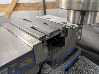
First, as mentioned before, I needed t slots on the top of one of the slides. I started by cutting with a 3/8" endmill:
PXL_20221001_001849930.jpg

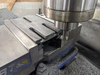
Then, my 10mm collet showed up and I was able to cut the t slots with the T cutter:
PXL_20221005_204528198.jpg

The slots are a bit "high" on the part, since I took about a week off between those operations and forgot I left the 3/8" slot about 50 thou "high". It shouldn't matter, and I can make it up with the T nuts.

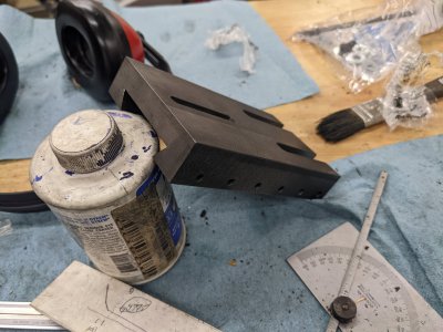
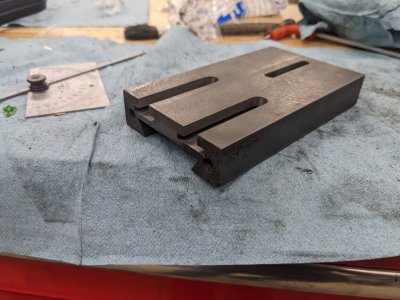
And the finished slide:
PXL_20221005_204551000.jpgPXL_20221005_204556361.jpg

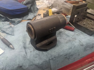
Next, I started with the work holding spindle. This part is similar to the one I scrapped, so I came up with an alternative for the lathe holding.

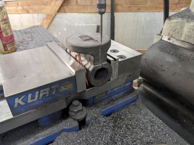
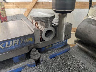
First, I put it on the mill to do the bottom. I used a wiggler to see the middle of the casting, since the casting line seemed about centered:
PXL_20221005_211037273.jpg

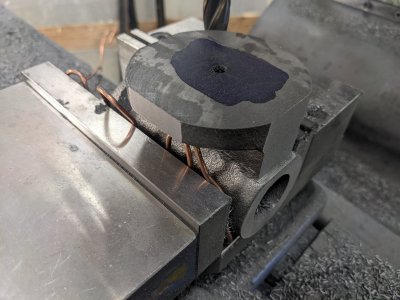
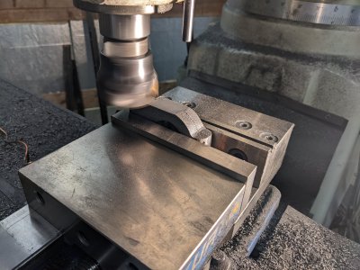
Next, I used a face mill to flatten the top, then a large 1" endmill to flatten the end face:
PXL_20221005_211938417.jpg
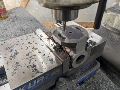
After that, I centered the pivot hole best I could, then drilled and reamed .250
PXL_20221005_213704774.jpg

The rotation slots seem to be an error on the plans, they say to make these 3/8", but they are for a 1/4" bolt, so I made them 1/4". I didn't think I could cut these from the top on a rotary table, nor could I figure out how to hold them that way, so I used the bolt circle setting on my DRO to plunge with a 1/64th over 1/4" endmill every 2 degrees:

PXL_20221005_221633496.jpg
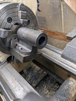
Next, the lathe parts, which scared me. I ended up finding an angle plate that I had in the shop that had bolt holes that lined up to bolt the part to, which I could then use to square in the lathe. It took some packing to get the jaws to not crash, and 6 hands to get in place, but it held!

I ended up starting at about 20rpm, and as I went, got comfortable up to almost 100!
PXL_20221005_225705441.jpg

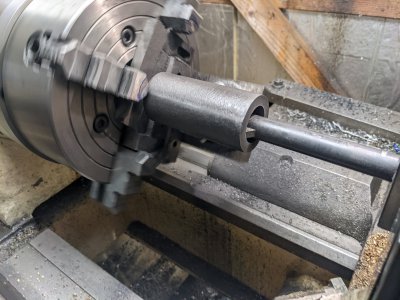
I cut the long inner bore first, which needs to fit a brass/bronze bushing from McMaster. I ended up being a wonderful press fit as speced!

PXL_20221005_232611116.jpg


I also had to do a larger bore for a bigger bushing, but only 1.5" through, not all the way. This one I ended up slightly oversized, so it is a "tight slip fit". I might end up loctiting it if necessary, but the shaft is supposed to squeeze these with the nut anyway.

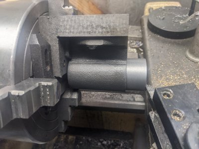
Next, I turned down the outer spot where a clamp holds another part in this. I went a little long, but figured this will be good for lining things up.PXL_20221006_002950995.jpg

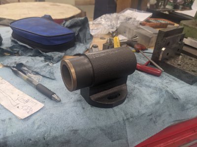
I pressed in the small bushing with the shaper vise, and pressed the bigger one in with my hands, and this part is complete as well!

PXL_20221006_003852911.jpgPXL_20221006_003857615.jpg

Whether I get shop time tomorrow is in the air, but next I'll probably work on the two parts that connect to the end of this work spindle body, as they are reasonablely easy and don't require special tooling I think.
 
One thing I found: My Mitutoyo DRO's bolt-circle is less featureful than the chinese one I had before! It ONLY takes start angle, diameter, number of holes, and center. NO end-angle! So I had to set my start angle, and choose 180 holes, then give up when I hit enough!
 
Time was limited today, but I got two parts done in the nick of time ;)

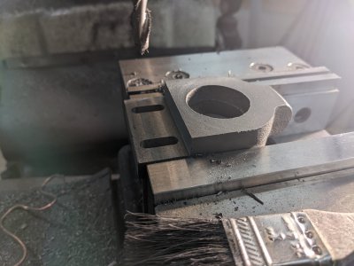
First, I worked on the worm gear holder clamp. This was as easy as facing a couple of sides:
PXL_20221006_201202030.jpgPXL_20221006_204136528.jpg

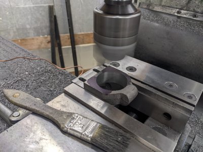
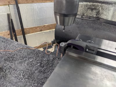
Then cutting a pair of slots and the main hole:

PXL_20221006_210951343.jpg

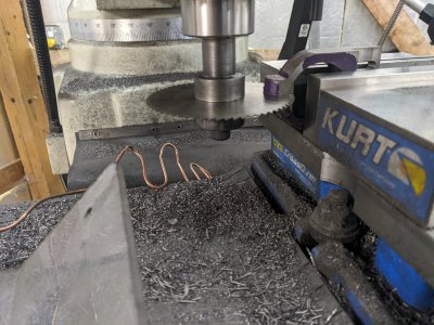
Next, just using a slitting saw to cut the clamp:
PXL_20221006_212246233.jpg

A quick facing cut, drill, and tap.
PXL_20221006_212915328.jpg
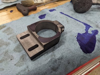
And, all done:
PXL_20221006_213504600.jpg

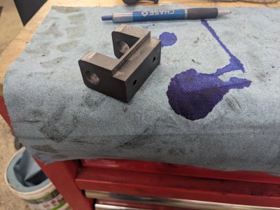
The next piece is the worm gear holder itself, which was just a bunch of squaring up, mixed with a couple of holes. I didn't get progress pictures, as I was coming against my time limit for the day:
PXL_20221006_225328545.jpg
 
You do nice work. Hey, do you already own the gear train for use with this?
 
Thanks! I don't actually. I was thinking about just buying a hob in the right size, having the gear set 3d printed, then remaking them all in aluminum as a way of trying out the machine :)
 
Thanks! I don't actually. I was thinking about just buying a hob in the right size, having the gear set 3d printed, then remaking them all in aluminum as a way of trying out the machine :)
Brilliant!
 
I'm new to this group, and your project definitely caught my eye. I've cut many gears using a specific gear cutter and dividing head, but I'm very interested to see how your gear hobber works out.
 
I'm new to this group, and your project definitely caught my eye. I've cut many gears using a specific gear cutter and dividing head, but I'm very interested to see how your gear hobber works out.
Thanks! I've done a good amount of those as well, but always find it nerve wracking to get them right! I'm hopeful these make gear cutting just trivial.
 
Very cool project and great work. Thanks for bringing us along! Keep the posts and pictures coming. I’ll certainly be following


Sent from my iPhone using Tapatalk
 
Back
Top